background image

7. VIDEO SIGNAL WAVEFORM DISPLAY 

30 


F•1 


7.4 

Adjusting the Intensity 

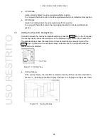
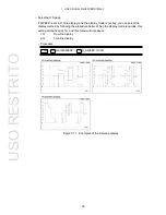
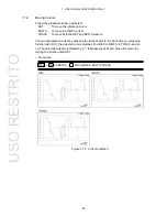
Follow the procedure shown in the figure below to access a menu that allows you to set items 

such as the scale unit and the intensity of the video signal waveform and scale. 


Figure 7-7  Intensity/scale configuration menu 


7.4.1 

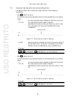
Adjusting the Video Signal Waveform Intensity 

You can adjust the video signal waveform intensity by following the procedure below. 

Adjustable range: -128 to 127 

•  Procedure 


→ 

INTEN/SCALE 

→ 

WFM INTEN:-128 to 0 to 127 


After performing the procedure described above, turn the function dial (F•D). Press the 
function dial 

(F•D) to return the intensity to its default value (0). 


F•1 

WFM 

USO 

RESTRITO

Summary of Contents for LV 58SER04

Page 1: ...LV 58SER04 MPEG DECODER INSTRUCTION MANUAL USO RESTRITO...

Page 2: ...3 10 ISDB T Display 6 2 3 11 General Specifications 6 3 COMPONENT NAMES AND FUNCTIONS 7 4 MENU STRUCTURE 8 4 1 Video Signal Waveform Display Menu 8 4 2 Vector Display Menu 10 4 3 Picture Display Menu...

Page 3: ...a Line 40 7 6 2 Setting the Line Select Field 40 7 7 Measuring with Cursors 41 7 7 1 Displaying Cursors 41 7 7 2 Selecting X Axis Y Axis Cursors 42 7 7 3 Selecting the Cursor Measurement Unit 42 7 7 4...

Page 4: ...hing the 4 3 Aspect Marker ON and OFF 67 9 2 2 Switching the 16 9 Aspect Marker ON and OFF 67 9 2 3 Displaying the Safe Action Marker 67 9 2 4 Displaying the Safe Title Marker 67 9 2 5 Displaying the...

Page 5: ...0 4 2 Selecting the Bit Rate Scale 87 10 4 3 Selecting the Bit Rates That Are Displayed 87 10 4 4 Highlighting the Selected Layer 88 10 5 Displaying ISDB T Broadcast Transport Streams 89 10 5 1 Displa...

Page 6: ...injury Do not apply external voltage to the output connectors Doing so may damage the device or lead to injury Table 1 1 Maximum input voltage Input Connector Maximum Input Voltage DVB ASI 2 V DC peak...

Page 7: ...io signals when combined with the LV 58SER40A 2 2 Features DVB ASI Input Connector The LV 58SER04 comes with one DVB ASI input connector Video Decoding The LV 58SER04 decodes compressed MPEG 2 TS vide...

Page 8: ...upported Standards ISO IEC 13818 1 Profile and Level MP HL MP ML 422 ML 422P HL 2 3 2 DVB ASI Input Input Connector Input Connector BNC R Number of Input Connectors 1 connector 75 Input Return Loss 20...

Page 9: ...ne Image QualityAdjustment Adjusts the brightness Vertical Axis Sensitivity V Scale 0 to 0 7 V 0 3 to 0 7 V Scale 0 to 100 50 to 100 Decimal Scale 0 to 255 Hexadecimal Scale 00 to FF Gain 1 5 variable...

Page 10: ...is convertedto SDTV Image QualityAdjustment Adjusts the brightness 2 3 6 Picture Displays HDTV Display Achieved through pixel sampling SDTV Display Achieved through pixel interpolation Marker Display...

Page 11: ...2 3 8 Dump Display Function Dumps the PAT PMT CAT NIT SDT BIT and the Notation selected packet Displays decimal and hexadecimal values andcontents 2 3 9 Bit Rate Display Function Bar Display Displaye...

Page 12: ...ent program_number fields the LV 58SER04 will have no way of decidingwhich one to use when it decodes and analyzes a stream The LV 58SER04 can decode streams with the following videoformats 1920 x 108...

Page 13: ...IN VARIABLE GAIN MAG SWEEP SWEEP MAG SWEEP MAG SWEEP MAG SWEEP MAG H_SWEEP V_SWEEP FIELD up menu LINE SELECT HDV SD HDV SDV HD SD ON OFF WHITE YELLOW CYAN GREEN MAGENTA RED BLUE CAL VARIABLE X1 X5 H V...

Page 14: ...hen COLOR MATRIX is set to COMPOSITE and H_SWEEP is set to2H 9 Appears when SWEEP is set to V 10 Appears when SWEEP is set to H and the OVLAY key is lighted 11 Appears when SWEEP is set to V the OVLAY...

Page 15: ...LECT SELECT FIELD up menu ON OFF FIELD1 FIELD2 FRAME COLOR COLOR SYSTEM MATRIX COMPOSITE FORMAT SETUP COLOR BAR up menu COMPONENT COMPOSITE AUTO NTSC PAL 0 7 5 100 75 PERSISTENCE PERSISTENCE PERSIST C...

Page 16: ...CENTER up menu ON OFF ON OFF ON OFF ON OFF LINE LINE SELECT SELECT ON OFF FIELD up menu FIELD1 FIELD2 FRAME DISPLAY MENU OFF SIZE HISTOGRAM up menu FIT REAL ON OFF Figure 4 3 Picture display menu 1 A...

Page 17: ...F1 F3 ON OFF CHAR SET up menu OVER WR YES OVER WR NO DELETE YES DELETE NO BITRATE DISPLAY HIGHLIGHT up menu CYCLE RESET SCALE MAX LAYER N LAYER A LAYER B LAYER C OFF 100 50 20 10 2 ISDB T DISPLAY LAY...

Page 18: ...set to ALL PID 4 Appears in the 1 or 4 screen displays 4 5 System Setup Menu UNIT SETUP UNITn SETUP SEMIAUTO PMT PID VIDEO PID SEL AUDIO PID SEL ERROR SETUP ON OFF COMPLETE PREV NEXT CANCEL PID DISP u...

Page 19: ...ADERagent You can install up to four LV 58SER04 units 5 2 Display When the LV 58SER04 is decoding an input signal properly it will display the signal information as shown in the figure below This sect...

Page 20: ...chroma difference formats and how they are indicated on the display Input Chroma Difference Format Display Indication YCBCR 4 2 2 YCBCR 4 2 0 YCbCr 422 YCbCr 420 3 Input Unit Number The input unit num...

Page 21: ...decodeand configure features such as error detection If there is more than one LV 58SER04 installed in the LV 5800 7800 you must set each LV 58SER04individually Procedure SYS F 1 UNIT SETUP F 1 to F 4...

Page 22: ...17 6 LV 58SER04 SYSTEM SETUP System Setup Display and Settings The following figure explains the system setup display and its settings Figure 6 2 PID selection display USO RESTRITO...

Page 23: ...if the LV 58SER04 reaches the end of the PATwithout finding a PID to decode You can manually set the PID in the MPEG 2 TS to be decoded even when semiautomatic PID selection is enabled When the autom...

Page 24: ...cannot set separate PMTs for audio and video Procedure SYS F 1 UNIT SETUP F 1 to F 4 SETUP select the unit number that corresponds to the slot that the LV 58SER04 is installed in F 2 PMT PID 6 1 3 Sel...

Page 25: ...Ds for decodable audio data Press F 4 AUDIOPID SEL to select the PID of the audio data to be decoded You cannot select PIDs that do not have AUDIO displayed to their right even if you move the cursor...

Page 26: ...ay shown in the figure below appears As long as the PAT is missing the LV 58SER04 will be unable toset a PID to be decoded Figure 6 4 Display when a PAT cannot be found The LV 58SER04 also refreshes t...

Page 27: ...you can switch detection on andoff and adjust the threshold values for errors defined as priority 1 by ETSI ETR 290 For more information about individual errors see section 10 1 1 Priority 1 Errors Pr...

Page 28: ...to determine PMTerrors This setting cannot be configured unless PMT Error is set to ON The PMT cycle can be set in the range of 100 to 800 ms in 10 ms steps The default setting is 500 ms PID Error Swi...

Page 29: ...enu you can switch detection on and off and adjust the threshold values for errors defined as priority 2 by ETSI ETR 290 For more information about individual errors see section 10 1 2 Priority 2 Erro...

Page 30: ...racy Error Switches PCR accuracy error detection on and off Default setting ON PTS Error Switches PTS error detection on and off Default setting ON PTS Cycle Sets the PTS repetition interval used to d...

Page 31: ...on andoff For information on these errors see section 10 5 Displaying ISDB T Broadcast Transport Streams Procedure SYS F 1 UNIT SETUP F 1 F 4 SETUP select the unit number that corresponds to the slot...

Page 32: ...Video signal waveform displaymenu When you display a video signal waveform using the LV 58SER04 the does not work and the external synchronization mode cannot be used 7 1 Adjusting the Waveform Displ...

Page 33: ...between the overlay and parade displays press the OVLAY key on the front panel The overlay display shows the waveforms in the selected display area on top of eachother The parade display shows the wav...

Page 34: ...ms of channels 1 to 3 on and off The CH1 to CH3 keys are lighted when the waveforms assigned to them are displayed They are not lighted when the waveforms assigned to them are not displayed Figure 7 6...

Page 35: ...d scale Figure 7 7 Intensity scale configurationmenu 7 4 1 Adjusting the Video Signal Waveform Intensity You can adjust the video signal waveform intensity by following the procedurebelow Adjustable r...

Page 36: ...rn the function dial F D Pressthe function dial F D to return the intensity to its default value 4 7 4 4 Setting the Scale Unit To change the scale units follow the procedure below This setting is val...

Page 37: ...RIX is set to YCbCr 255 FF INTEN SCALE SCALE UNIT HDV SD HDV SDV HD SD When COLOR MATRIX is set to GBR or RGB INTEN SCALE SCALE UNIT HDV SD HDV SDV HD SD 150 255 FF scale V scale 150 scale 255 scale F...

Page 38: ...rs The scale is displayed when you set 75 COLOR SCALE to ON This setting only appears when COLOR MATRIX is set to YCbCr Procedure INTEN SCALE 75 COLOR SCALE OFF ON Figure 7 9 Scale lines for 75 intens...

Page 39: ...FORM DISPLAY 34 7 5 Adjusting the Gain Follow the procedure shown in the figure below to display a menu for adjusting the video signal waveform vertical and horizontalgains Figure 7 10 Gain adjustment...

Page 40: ...ow shows the gain ranges that can be set byusing F 2 GAIN MAG GAIN VARIABLE and Table 7 2 Video signal waveform vertical gain adjustableranges GAIN VARIABLE CAL VARIABLE GAIN MAG 1 1 0 200 to 2 000 5...

Page 41: ...is overlay you can selectthe display method by following the procedure below When the display mode is parade this setting will be fixed at 1H and this menu will not appear 1H One line display 2H Two l...

Page 42: ...the procedure below When the displaymode is parade or when the input signal is progressive this setting will be fixed at 1V and this menu will not appear 1V One frame display when the input signal isp...

Page 43: ...MATRIX is set to COMPOSITE Figure 7 13 Zoom focus line on the 0 V scale line ACTIVE Displays waveforms expanded excluding the H blanking interval of the input video signal This option is not displayed...

Page 44: ...input signal is interlaced and V_SWEEP is set to 1V FIELD1 The video signal waveform for field 1 appears FIELD2 The video signal waveform for field 2 appears Procedure GAIN SWEEP FIELD FIELD1 FIELD2...

Page 45: ...number Figure 7 16 Line number selection 7 6 2 Setting the Line Select Field Follow the procedure below to set the line selection range This menu does not appear when the input signal is progressive Y...

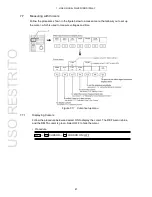
Page 46: ...hat allows you to set up the cursor which is used to measure voltages and time Figure 7 17 Cursor setup menu 7 7 1 Displaying Cursors Follow the procedure below and select ON to display the cursor The...

Page 47: ...f the display in the type of unit that you select here Y axis units mV The voltage is displayed In component display the percentage of 700 mV is displayed In pseudo composite display the percentage of...

Page 48: ...and DELTA cursors You can also select a cursor by pressing the function dial F D Each time you pressthe function dial F D the selected cursor switches from REF to DELTA to TRACK and so on The selected...

Page 49: ...itude When Y UNIT is set to R the amplitude when F 5 REF SET is pressed is 100 This menu does not appear when XY SEL is set to X or when Y UNIT is set to something besides R Procedure WFM CURSOR REF S...

Page 50: ...setup menu 7 8 1 Setting the Type of Filter When COLOR MATRIX is not set to COMPOSITE follow the procedure below toselect one of these video signal filters FLAT A filter with a flat frequency response...

Page 51: ...side by side with the chroma difference signal FLAT Only displays the pseudo composite signalwaveform FLAT LUM Displays the pseudo composite signal waveform and the luminance signal side by side LUM C...

Page 52: ...Waveforms are persistent OFF Waveforms are not persistent INFINIT Waveforms persist until they are cleared or until the screen display mode is changed Procedure WFM INFINIT ARRANGE PERSISTENCE PERSIST...

Page 53: ...ay color matrix Figure 7 24 Color system setup menu 7 9 1 Configuring the Waveform Display Color Matrix When the LV 58SER04 receives luminance and chrominance signals it can use matrix calculation to...

Page 54: ...aveform RGB Converts the YCBCR signal into an RGB signal and displays the RGB waveform COMPOSITE Displays a component signal artificially as a NTSC or PALcomposite signal Color burst frequencies do no...

Page 55: ...3 Setting the Video Signal Display Format for the Pseudo Composite Display When you have selected pseudo composite display follow the procedure below to set the display to NTSC or PAL You can also ch...

Page 56: ...o select one of these pseudo composite signal setup levels You can only select a setup level when displaying an NTSC pseudo composite signal This setting is not available when a component or PAL signa...

Page 57: ...ys based on CB horizontal and CR vertical Figure 8 1 Vector display menu Table 8 1 Video signal formats and compatible colorimetry standards Scale Video Signal Format Settings Compatible ColorimetrySt...

Page 58: ...I and Qaxes Figure 8 2 Intensity scale configurationmenu 8 2 1 Adjusting the Vector Waveform Intensity You can adjust the vector waveform intensity by following the procedurebelow Procedure INTEN SCAL...

Page 59: ...re INTEN SCALE VECTOR COLOR WHITE GREEN 8 2 3 Adjusting the Scale Intensity You can adjust the scale intensity by following the procedure below Procedure INTEN SCALE SCALE INTEN 8 to 4 to 7 After foll...

Page 60: ...you display an HDTV signal the full scale value of 0 7 V is set at 100 I axis G 44 559 Q axisG 37 056 B 27 865 B 84 085 R 69 120 R 62 417 Procedure INTEN SCALE IQ AXIS ON OFF Figure 8 3 Displays with...

Page 61: ...nuously vary the gain To adjust the gain follow the procedure below and choose one of thesesettings CAL 1 VARIABLE 0 200 to 2 000 You can adjust the gain by turning the function dial F D The value app...

Page 62: ...circle the LV 58SER04 sets the gain at 3 140 when it receives anSMPTE color bar signal Procedure GAIN GAIN MAG 1 5 IQ MAG 8 4 Selecting Lines You can use the vector waveform display line select functi...

Page 63: ...selected line number is indicated in the lower left of the display Figure 8 7 Vector waveform display when the line select feature is enabled 8 4 2 Selecting a Field Follow the procedure below to sele...

Page 64: ...gnal but you can display pseudo composite signal vectors by converting the signal into a pseudo composite signal You can also set the setup value and the color barsaturation Follow the procedure shown...

Page 65: ...ure COLOR SYSTEM COLORMATRIX COMPONENT COMPOSITE Figure 8 9 Component and composite displays 8 5 2 Setting the Video Signal Display Format for the Pseudo Composite Display When you have selected pseud...

Page 66: ...TSC pseudo composite signal This setting is not available when a component or PAL signal is displayed 0 No setup 7 5 Adds a setup of 7 5 Procedure COLOR SYSTEM SETUP 0 7 5 8 5 4 Setting the Color Bar...

Page 67: ...eforms and present waveforms at the same time Follow the procedure below and choose one of thesesettings ON Waveforms are persistent OFF Waveforms are not persistent INFINIT Waveforms persist until th...

Page 68: ...5800 panel to access the picture display and the picturedisplay Figure 9 1 Picture display procedure The picture display may not display the two lines of pixels farthest to the left right top and bott...

Page 69: ...e below Figure 9 2 Picture display adjustmentprocedure 9 1 1 Adjusting the Brightness Follow the procedure below to adjust the picture displaybrightness You can adjust the brightness within the range...

Page 70: ...ADJUST ADJUST ADJUST GAIN GAIN GAIN R GAIN 0 70 to 1 00 to 1 30 G GAIN 0 70 to 1 00 to 1 30 B GAIN 0 70 to 1 00 to 1 30 After performing the procedure described above turn the function dial F D to ad...

Page 71: ...the marker display menuand display various kinds of markers Safety markers appear when SIZE is set to FIT and MENU is not set to OFF Figure 9 3 Marker display menu There are four different marker siz...

Page 72: ...afe titlemarker To turn the 16 9 aspect marker on or off follow the procedurebelow Procedure MARKER 16 9 ON OFF 9 2 3 Displaying the Safe Action Marker You can display a safe action marker with a widt...

Page 73: ...ER CENTER ON OFF 9 3 Displaying the Line Marker You can use the picture display line select feature to confirm the location of a specific line number The line marker appears when SIZE is set to FIT an...

Page 74: ...e Selection Follow the procedure below to select a line selection range within the picture display You cannot select a field when the video signal format isprogressive FIELD1 The line selection range...

Page 75: ...one pixel from the video signal is displayed using one pixel on the LCD Follow the procedure below to access the picture display format menu and choose one ofthese settings FIT The picture size is adj...

Page 76: ...t each brightness level on the vertical axis Dark points are displayed on the left of the histogram and bright points are displayed on the right Procedure DISPLAY HISTOGRAM ON OFF Figure 9 9 Histogram...

Page 77: ...ing the Error Status The first status display that appears when you press STATUS key is the error status display When you press STATUS key the function menu becomes the status display menu Youcan acce...

Page 78: ...TS_error Checks for PTS transmission intervalerrors CAT_error Checks for CAT errors ETC Items that are not defined by ETR 290 PCR JITTER The amount of PCR jitter with respect to the reference clock 10...

Page 79: ...ol allows the same packet to be sent twice in a row Even in this case because the continuity_counter of each packet is the same the LV 58SER04 will indicate a continuity error PAT_error The LV 58SER04...

Page 80: ...if the PCR repetitioninterval exceeds the specified time The only PCRs that are monitored for repetition are those listed in the PMT to be decoded PCRs not listed in the PMT to be decoded are not mon...

Page 81: ...a section with a CAT PID 0001h is not 01 in hexadecimal The CAT repetition interval exceeds the specified time To set the time adjust the CAT Cycle setting in error detection setup 2 Thedefault time...

Page 82: ...isplayed Procedure EVENTLOG Figure 10 2 Event log menu General Event Log Explanation Events are listed on the event log screen by the time of theiroccurrence By turning the function dial F D to the ri...

Page 83: ...of Packets LN detection ISDB T PKT_A NG has been displayed for the result of Number of Packets LA detection ISDB T PKT_B NG has been displayed for the result of Number of Packets LB detection ISDB T...

Page 84: ...ventlog Procedure EVENT LOG CLEAR 10 2 3 Setting the Event Log Overwrite Mode The LV 5800 7800 can display up to 5000 events Carry out the procedure below to select the action to perform when more tha...

Page 85: ...the procedure below 1 Connect a USB memory device to the USB port 2 Press USB MEMORY The file list screen appears This command appears when the LV 5800 has USB memory connected to it Figure 10 3 File...

Page 86: ...wait disappears the file hasbeen successfully saved If a file with the same name that you have specified already exists on the USB memory device an overwrite confirmation menu appears If you want to...

Page 87: ...nly shows the data contained in the PAT andPMTs Decoded PIDs are displayed in green Up to 544 multiplexed data entries and 1024 lines can be displayed Any additional data entries are not displayed If...

Page 88: ...an example of dumped PATdata The dump display is based on IEC 13818 1 If the dumped information does not fit into one screen you can scroll through it using the function dial F D Even with scrolling...

Page 89: ...tion that is written in all PMT packets Procedure TREEDISPLAY ALLPMT DETAILS OPEN CLOSE OPEN CLOSE Figure 10 7 Expanded display of PMTpackets If you want to expand and display the information that is...

Page 90: ...or N is shown on the PID tree display Follow the procedure below to highlight all the entries that are from the same layer as the layer that you have selected All entries from other layers will be dis...

Page 91: ...contain PCRs All bit rates are displayed in a numeric display and in a bar graph display on the right side of the screen The bar graph shows bit rates as a percentage of the TS bit rate The bit rate d...

Page 92: ...layed in red Procedure BITRATEDISPLAY SCALE MAX 100 50 20 10 2 100 2 Figure 10 11 Bar graph display 10 4 3 Selecting the Bit Rates That Are Displayed Follow the procedure below to display the bit rate...

Page 93: ...pplied and F 5 DISPLAY is set to ALL PID followthe procedure below to highlight the layer that you have selected All entries from other layers will be displayed in gray This menu does not appear when...

Page 94: ...ried out successfully Any values in the input signal that are outside of the standards are displayed in yellow If you do not turn error detection on for Number of Packets Frm Continuity and CRCerrors...

Page 95: ...ts LN Packets Frm Continuity The LV 58SER04 examines the continuity of the ISDB T information section s TSP counter If it is not continuous NG is displayed CRC error TMCC Displays the result of checki...

Page 96: ...ata Pos Displays the position where AC data is multiplexed System Identifier Displays the TMCC identifier Sw On Ctrl Flag Displays whether the emergency broadcast system flag is ON orOFF CRC32 Display...

Page 97: ...dded to the picture display of the LV58SER04 PACKET_SIZE has been added to the LV 58SER04 status display ASI_FORMAT has been added to the LV 58SER04 status display for LV 58SER04 FPGA versions 0121 an...

Page 98: ...tem vector display 59 video signal waveform display 48 COMPOSITE FORMAT 50 60 Continuity 74 Continuity Error 23 CONTRAST 65 contrast adjustment 65 CRC Error 25 CRC_error 75 cursor 41 display 41 refere...

Page 99: ...9 LOG MODE 79 M markers 66 MENU OFF 71 menu structure 8 O overlay display 28 OVLAY key 28 P PACKET_SIZE 76 parade display 29 PAT Cycle 23 PAT Error 23 PAT_error 74 PCR Accuracy Error 25 PCR Cycle 25 P...

Page 100: ...status display menu 12 STATUS key 72 SWEEP 35 sweep adjustment 35 SWEEP MAG 38 Sync Byte Error 23 Sync_byte_error 74 system setup 16 system setup menu 13 T TMCC 90 TMCC interpreted 90 Transport 75 Tra...

Page 101: ...Following information is for Chinese RoHS only LV 58SER04 2006 2 28 SJ T11364 2006 Parts Hazardous Substances in each Part Pb Hg Cd Cr PBB PBDE SJ T11363 2006 SJ T11363 2006 Ver 2 USO RESTRITO...

Page 102: ...LEADER ELECTRONICS CORP 2 6 33 Tsunashima Higashi Kohoku ku Yokohama 223 8505 Japan PHONE 81 45 541 2123 FAX 81 45 541 2823 http www leader co jp Oct 14 2010 Ver 6 FW Ver 6 8 USO RESTRITO...

Reviews: