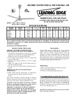
ASSEMBLY INSTRUCTIONS & PARTS MANUAL FOR
COMMERCIAL CEILING FANS
CEILING FANS SHOULD BE INSTALLED
BY QUALIFIED INSTALLER.
MODEL
NUMBER
BLADE
SWEEP
COLOR
VOLTAGE
MAX
HZ
MAX
RPM
MAX
AMPS
WATTS
WT
(LBS)
36201
48201
48201B
56001LC
48203*
56003*
36”
48”
48”
56”
48”
56”
White
White
Black
White
White
White
120
120
120
120
120
120
50/60
50/60
50/60
50/60
50/60
50/60
395
315
315
265
315
265
.65
.85
.85
1.0
.86
1.0
75
86
86
110
80
110
20
22
22
24
23
26
READ INSTRUCTIONS CAREFULLY BEFORE ATTEMPTING TO ASSEMBLE OR SERVICE THE LEADING EDGE
CEILING FAN. FAILURE TO COMPLY WITH INSTRUCTIONS COULD RESULT IN PERSONAL INJURY AND/OR
PROPERTY DAMAGE.
RETAIN FOR FUTURE REFERENCE.
General Safety Information
WARNING: DISCONNECT POWER BEFORE
INSTALLING OR SERVICING THIS EQUIPMENT.
1. All electrical wiring should be done by a qualified
electrician in accordance with applicable National
Electrical Code and local electrical codes.
2. Do not allow moving blades to come in contact with
any part of the body.
3. Mount fan so that fan blades are 7 feet or higher
from floor.
4. Make sure hanger hooks are mounted securely to
structural ceiling members.
5. Do not mount in an area which will allow the fan to
get wet.
WARNING: DO NOT USE IN AN EXPLOSIVE
ATMOSPHERE.
6. Make certain that the ground wire is connected to
the ground terminal and to a suitable electrical
ground.
NOTE: When mounted in cathedral ceilings, the blade tip
should be at least 12 inches from the angled roof line to
prevent air “blow back” causing possible fan sway.
CAUTION: Read and follow instructions carefully.
Failure to comply with instructions could result in
the risk of fire, shock and injury to persons.
WARNING: TO REDUCE THE RISK OF PERSONAL
INJURY DO NOT BEND THE BLADE BRACKETS
WHEN INSTALLING THE BRACKETS OR CLEANING
THE FAN. DO NOT INSERT FOREIGN OBJECTS IN
BETWEEN ROTATING FAN BLADES.
Description
Leading Edge Fans are designed as a dual purpose
product. By minimizing temperature stratification in
winter, they can reduce heating costs in high bay
buildings. The summertime application provides a gentle
downward movement of air for general air recirculation
and evaporative cooling. A permanent split capacitor
motor and permanently lubricated ball bearings add to
the efficiency and quietness of the fans.
Unpacking
1. Remove fan components from carton carefully.
2. Check for shipping damage.
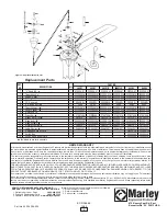
3. Check for missing parts against parts list.
RECOMMENDED MOUNTING HEIGHTS
For heat reclamation, this fan should be mounted on the
standard 2’ downrod included. In low ceiling applications,
the 8” downrod must be used in order to keep the fan
blades a minimum of 7’ from the floor. On installations
through drop ceilings, note the diameter of the downrod
hole in the ceiling should be 2
1
/
2
”.
CAUTION: Fan blades should not be mounted lower
than 7 feet above the floor.
MODEL: 36201, 48201, 56001LC
48203, 5600-3, 48201B
SPECIFICATIONS
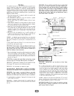
*This ceiling fan is operated by a pull chain switch which controls the three speeds: 0-off, 1-low, 2-medium, 3-high. (See figure 5 for illustration)


