Tel: +44 (0)1981 241668
Skyrrid Farm, Pontrilas, Hereford. HR2 0BW. UK
www.leturbines.com
Page 10 of 28
6)
Install the Transmission Cables- Follow the table below to select the correct wire size
(cross-sectional area). This will vary depending on your nominal battery voltage and the
distance that the cables will be run. Careful selection of the cable size is required. It will
not only affect the safety of the system, but also the overall efficiency. A cable of
insufficient cable size will cause a voltage drop, wasting the power that has been
generated. The cable sizes listed below have been selected with efficiency and cost in
mind, as it is unlikely that your turbine will be running at full capacity 100% of the time. If
in doubt, consult your local electrical supplier. The cable should be installed in accordance
with local electrical regulations and guidelines. If in doubt, use a local electrical contractor
to complete the cable installation. Once the transmission cable installed, it can be
connected to the LE-v150.
Warning: If a cable of insufficient cross-sectional area is used, heat will build up in the cables
causing a potential fire hazard. Cable capacities quoted below are based upon ‘Tri-Rated’ cables
(BS6231).
Transmission Distance
LE-v150 Nominal
Output Voltage
10 Metres
(30 Feet)
30 Metres
(90 Feet)
100 Metres
(300 Feet)
12 Volts
1.5 mm²
4 mm²
Not Recommended
24 Volts
1.5 mm²
2.5 mm²
10 mm²
48 Volts
1.5 mm²
1.5 mm²
4 mm²
Electrical Installation
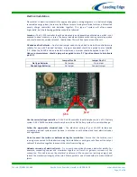
Please refer to Fig 4 for appropriate generic wiring diagrams. In a battery charging renewable
energy system there may be different ways of wiring small wind turbines, photovoltaic panels,
charge controllers and batteries together. This type of system will often expand ‘organically’, but
the following guidelines should be followed:
Follow the appropriate electrical code - The electrical wiring of your LE-v150 turbine and
associated electrical systems must be done in accordance with national and local electrical
codes and regulations.
Do not connect the turbine or batteries during the installation - Ensure that the turbine is
not running or connected to the batteries during the installation or wiring process.
Connect the output cables of the turbine together to prevent the rotor from starting up.
Galvanic corrosion of electrical joints - Try to avoid connections between dissimilar
metals. For example, connecting copper and aluminium together will result in galvanic
corrosion of the connection. This will increase the electrical resistance of the connection
(wasting energy), and reduce the mechanical integrity of the joint. Where possible, use a
fluxed solder to make electrical joints.
Protect the cables - The power transmission cables must be protected from mechanical
damage and fatigue. Run the cables through an approved conduit / trunking.
Cable strain relief - Prevent mechanical strain on the transmission cables running down
the tower from the turbine. Clip the cables to the inside of the tower. Failure to do this will
result in excessive mechanical strain on the cable joints within the slip-ring assembly and
may cause a failure. Cable ties or cable glands are a good way to prevent mechanical strain
on the cables.

