background image


Tel: +44 (0)1981 241668 

Skyrrid Farm, Pontrilas, Hereford. HR2 0BW. UK 

           www.leturbines.com  


 Page 18 of 28


Damage  caused  by  incorrect  connection  to  external  electrical  equipment,  or  failure  to 
observe  current  regulations  concerning  connection  to  external  electrical  networks, 
equipment or any other devices. 

 
If you should experience a problem with your turbine, your first ‘port-of-call’ should be the reseller 
or  installer  from  whom  you  purchased  the  product.  They  should  be  able  to  resolve  the  problem 
quickly  and  efficiently.  If  you  are  unable  to  contact  the  original  reseller,  then  please  contact  us 
directly. 
 
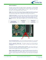
Please  quote  the  serial  number  of  your  turbine  when  dealing  with  warranty  issues.  The  serial 
number can be found on the nameplate positioned on the underside of the chassis. 


Disclaimer 


All specifications are subject to change without prior notice. 


The information given in this user manual is believed to be accurate and reliable.  Leading 
Edge Turbines
 assumes no responsibility for omissions or inaccuracies. 


The user of this information and product assumes full responsibility and risk. 


The LE-v150 turbine is a source of electrical power. It must be installed in accordance with 
local  building  and  electrical  regulations.  Consult  your  local  planning  (zoning)  office  for 
details. 


The LE-v150 turbine has moving parts that may cause injury due to poor installation and 
unsafe operation. Leading Edge Turbines assumes no responsibility for problems caused by 
unsafe or unsatisfactory installation or operation. 


Designed & Manufactured in the UK by: 

Leading Edge Turbines Ltd 

Skyrrid Farm, 

Pontrilas, 

Hereford. 

HR2 0BW 

Tel: +44 (0)1981 241668 

www.leturbines.com


Compliant with 

EN BS 61400-2: Safety of Small Wind 

Turbines 

Summary of Contents for GA-LETU-013

Page 1: ...m Pontrilas Hereford HR2 0BW UK www leturbines com Page 1 of 28 LE v150 LE v150 Extreme Turbine Installation Operation Guide A silent and robust vertical axis wind power for a range of off grid applic...

Page 2: ...lation 10 Turbine Operation 13 Maintenance 15 Spares 16 Warranty 17 Disclaimer 18 Appendix 1 DL 300 Charge Controller User Manual 20 Appendix 2 Run Stop Switch User Manual 24 Warranty Registration Ple...

Page 3: ...on charge controller optional always ensure that the turbine and the controller are connected to the battery separately 3 Don t allow the turbine to run without being connected to the battery Failing...

Page 4: ...to ensure optimum efficiency and a long operating life Specific LE v150 turbine features Innovatively designed axial flux alternator using neodymium iron boron magnets Bearing support at both ends of...

Page 5: ...completed at ground level Ensure that the batteries are disconnected during the installation procedure Twist the turbine output cables together to create a short circuit during the mechanical install...

Page 6: ...Part Number GA LETU 013 Turbine Name LE v150 Extreme Part Number GA LETU 023 Nominal Voltage 12V 24V 48V DC Rotor Diameter 270 mm Rated Wind Velocity 8 m s Rated Output 24 Watts Start up Wind Velocity...

Page 7: ...r dealer immediately Tools Required For Assembly You will require the following tools to assemble your LE v150 turbine 13 mm A F spanner 13 mm ratchet one of each required 8mm A F spanner or ratchet A...

Page 8: ...ly E Retighten the upper and lower stub shaft fixings and check that the turbine still rotates freely F Reposition and fix the cowlings ensuring that they do not rub upon each other The bearing units...

Page 9: ...e turbine removed from the baseboard it can now be fitted in its intended position The LE v150 is supplied as standard with three universal flat mounting brackets Dimensions of the brackets can be fou...

Page 10: ...generic wiring diagrams In a battery charging renewable energy system there may be different ways of wiring small wind turbines photovoltaic panels charge controllers and batteries together This type...

Page 11: ...etween the switch and the batteries Run Stop Switch A simple switch arrangement can provide a safe and easy way of stopping the turbine for maintenance Leading Edge Turbines can supply a switch which...

Page 12: ...Tel 44 0 1981 241668 Skyrrid Farm Pontrilas Hereford HR2 0BW UK www leturbines com Page 12 of 28 Fig 4 Simple Stand Alone battery charging wiring diagram...

Page 13: ...Tel 44 0 1981 241668 Skyrrid Farm Pontrilas Hereford HR2 0BW UK www leturbines com Page 13 of 28 Fig 6 Typical Hybrid wind PV System wiring diagram...

Page 14: ...tor speed increases so too will the current and voltage Shut Down If Run Stop switch is fitted A run stop switch is not required with the LE v150 turbine but one can be installed if desired see append...

Page 15: ...If many dents have occurred along the edges of the blades a new set of rotor blades should be fitted part numbers available in the Spares section Remove any build up of dirt and debris from the rotor...

Page 16: ...Dealer and quote the part numbers listed below Rotor Blade set of 3 DP LETU 303 x3 Bearing Housing DP LETU 198 Bearing Service Kit OS 296 Stator 12 VDC SA LETU 005 12V Stator 24 VDC SA LETU 005 24V St...

Page 17: ...rranty and may compromise the safety of the machine What is not covered by your warranty Damage caused by unsatisfactory installation of the turbine tower and or control equipment Damage caused by the...

Page 18: ...side of the chassis Disclaimer All specifications are subject to change without prior notice The information given in this user manual is believed to be accurate and reliable Leading Edge Turbines ass...

Page 19: ...Tel 44 0 1981 241668 Skyrrid Farm Pontrilas Hereford HR2 0BW UK www leturbines com Page 19 of 28 Appendix 1 DL 300 Charge Controller User Manual...

Page 20: ...The DL 300 Features PWM Pulse Width Modulation for highest charging performance without flicker Selectable three stage charging or over voltage protection mode Selectable for sealed or flooded batter...

Page 21: ...hat the correct size of cable has been selected If a cable of insufficient cross sectional area is used at any point in the electrical system heat will build up in the cables causing a potential fire...

Page 22: ...s should a jumper be applied to pins 2 1 position shown to help locate pins 2 2 Jumper Pins 2 1 Jumper Pins 2 2 Gel type Batteries No Jumper No Jumper Flooded type Batteries No Jumper Connect Jumper U...

Page 23: ...ating The fuse or breaker should be positioned between the DL 300 and batteries on the positive cable DL 300 Voltage Set Points Whilst operating the DL 300 does a multi stage charge based on time and...

Page 24: ...Tel 44 0 1981 241668 Skyrrid Farm Pontrilas Hereford HR2 0BW UK www leturbines com Page 24 of 28 Appendix 2 Run Stop Switch User Manual Only operate in light winds...

Page 25: ...peated dynamic braking operations The switch has two positions Position 1 Turbine Stop position The turbine is dynamically braked and may be seen to rotate very slowly Position 2 Turbine Run position...

Page 26: ...move batteries by yourself Always use manual handling tools and an assistant Always keep lead acid batteries the correct way up Do not allow the acidic electrolyte to spill or come into contact with y...

Page 27: ...Tel 44 0 1981 241668 Skyrrid Farm Pontrilas Hereford HR2 0BW UK www leturbines com Page 27 of 28...

Page 28: ...arm Pontrilas Hereford HR2 0BW UK www leturbines com Page 28 of 28 Contact Us Your Local Distributor Leading Edge Turbines Ltd Skyrrid Farm Pontrilas Hereford HR2 0BW UK Tel 44 0 1981 241 668 info let...

Reviews:

Related manuals for GA-LETU-013