


Tel: +44 (0)845 652 0396
Skyrrid Farm, Pontrilas, Hereford. HR2 0BW. UK
www.leturbines.com
Page 17 of 47
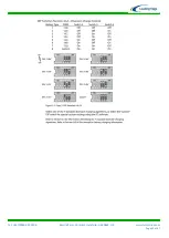
Turbine Operation
The LE-450 turbine is based on a simple design for ease of installation and reliable operation. You
may notice the following behaviour during normal operation:
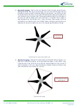
Cut-in - The turbine will not begin to charge the batteries until the rotor is spinning at
approximately 300 RPM. Whilst operating below this speed, the turbine will be ‘off-load’
and freewheeling. Once the turbine output voltage becomes equal to the nominal battery
voltage (at around 300 RPM), the turbine will come ‘on-load’ and begin to deliver current
to the batteries. During the off-load stages of rotation, the rotor blades rotate very freely.
This allows the rotor to build up speed and allows aerodynamic lift to be generated by the
blades.
Normal Operation - Once the rotor is spinning at 300 RPM, current will be delivered to the
batteries. As the rotor speed increases, so too will the current and voltage. Excessive wind
speed may increase the battery voltage to a high level. Once this happens the diversion
charge controller will recognise that the battery voltage is too high and begin 'dumping'
power to the heater module.
Charge Regulation - Once the charge controller has switched over to the dump load, the
turbine will no longer be charging the batteries. Instead, the power from the turbine will
be delivered to the dump load (usually a resistive heater element). The battery voltage will
begin to drop to normal levels during the regulation period. Once the battery voltage is
back within acceptable limits, the charge controller will switch the turbine output back to
the batteries. Refer to the charge controller user manual for specific operational
instructions.
Shut Down - By activating the stop switch, the output from cables of the turbine are
‘shorted’ together. This effectively puts an infinite load on the generator causing the
turbine to stall. When the stop switch is activated the turbine may still rotate slowly during
high winds, but the rotor blades will not be able to build up any significant speed. It is not
recommended that the stop switch is activated whilst the rotor is spinning at high speed.
This sudden braking action will stress the blades and other components. Only activate the
stop switch during a ‘lull’ when the rotor is not spinning excessively fast.
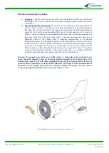
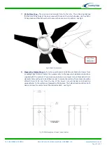
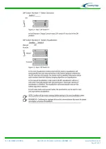
Warning – Using the Run /Stop Switch in strong winds > 40 mph.
In certain strong wind conditions the rotor can overpower the electromagnetic braking,
which allows high currents to be produced in the stator coils. If this situation occurs for
prolonged periods, damage to the turbine can occur. Therefore the Run / Stop switch
should only be used to slow the unit prior to manually / mechanically tethering the
turbine in very high winds. Either restrain the blades or swing the turbine to 90 degrees
away from the wind and tether it in this position. A hole for tethering is provided in the
tail-fin of the LE-450 (see Fig 16).
Operation of the LE-450 in High Winds - Every effort has been taken to ensure that the LE-
450 will withstand the forces exerted by strong winds. However the raw power in high
winds is immense and the stresses placed upon the turbine are magnified by gusty and
turbulent conditions. Where possible the turbine should be shut down and tethered in
advance of particularly strong, consistent winds (60+ mph) and storm conditions. This will
decrease the wear and tear on the machine and will help to avoid a failure. Protect the
turbine from extreme winds as you would protect other items of your property.
Refer to
the Shut Down procedure above.
Summary of Contents for GA-LETU-016
Page 47: ......


