background image


Tel: +44 (0)845 652 0396 

Skyrrid Farm, Pontrilas, Hereford. HR2 0BW. UK 

           www.leturbines.com  


 Page 40 of 47


Introduction 

 
Please  read  this  manual  thoroughly  before  attempting  to  assemble,  install  or  operate  your 
Universal Run / Stop Switch. This will assure optimum performance and safety. 
 
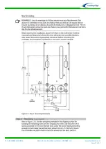
The  Universal  Run  /  Stop  Switch  is  designed  to  allow  the  user  to  dynamically  brake  an  LE-450 
turbine at will. This is achieved by disconnecting the power output of the turbine from the relevant 
load  and  diverting  it  to  a  short  circuit  which  then  applies  the  dynamic  braking  effect  on  the 
permanent  magnet  alternator  of  the  turbine.  This  will  bring  the  turbine  to  a  near  stop  for 
maintenance only. 
 
The Universal Run / Stop Switch can be used with turbines of different manufacture as long as the 
relevant turbine has the following characteristics: 
 
3-Phase Wild AC not exceeding 500 V & 16 A 
Wild DC not exceeding 150 V & 10 A 
Mechanically and electrically capable of dynamic braking 
 
 
Operation & Specification 
 
The  Universal  Run  /  Stop  Switch  should  be  operated  during  low  speeds  as  repeated  use  at  high 
speeds may cause damage if the turbine head (it was not designed to withstand repeated dynamic 
braking operations). 
 
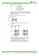
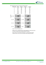
The switch has two positions: 
 
Position  1:  Turbine  'Stop'  position.  The  turbine  is  dynamically  braked  and  may  be  seen  to  rotate 
very slowly. 
 
Position 2: Turbine 'Run' position. The turbine output is allowed to flow straight through the switch 
to the relevant output. 
 
Safety Precautions 
 
Safety must always be your primary concern during the assembly, installation and operation of your 
turbine  and  other  associated  equipment.  Always  be  aware  of  the  risks  involved  with  mechanical 
and electrical installation work. If in doubt about any issue regarding your turbine system, please 
seek further assistance before proceeding.  
 
Mechanical Safety Hazards: 
Whilst installing the Universal Run / Stop Switch, ensure that the turbine is suitably restrained and 
not allowed to operate during the installation. 
 
Electrical Safety Hazards: 
The  LE-450  generates  rectified  DC  voltage  and  the  Universal  Run  /  Stop  Switch  also  operates  at 
these voltages. Even at these low voltages there are inherent risks. Caution should always be used 
when connecting the LE-450 or other equipment to the electrical system.  
 
Ensure that you have followed the cable-sizing  guidelines  to ensure that the  correct  size of cable 
has been selected. If a cable of insufficient cross-sectional area is used at any point in the electrical 
system,  heat  will  build  up  in  the  cables  causing  a  potential  fire  hazard.  A  properly-sized  fuse  or 
circuit breaker should be used in the cables connected to the battery. This will stop the risk of short 
circuit currents. 
 

Summary of Contents for GA-LETU-016

Page 1: ...d Farm Pontrilas Hereford HR2 0BW UK www leturbines com LE 450 Turbine Installation Operation Guide 1m Diameter Micro Wind Turbine for generating clean and renewable electricity anywhere the wind blow...

Page 2: ...Installation Checks to be carried out one month after installation 19 Annual Maintenance 19 After five years of normal operation 19 Other Considerations 19 Spares 20 Warranty 21 Disclaimer 22 Appendi...

Page 3: ...ed to the battery separately Ensure the blades are fitted in the correct orientation Consult the diagram on page 9 Blades fitted back to front it will severely impair power production Don t allow the...

Page 4: ...ser cut aluminium chassis using Yaw wing design to ensure responsive yawing and to reduce weight Maintenance free low friction bearing in both main shaft and yaw assemblies Extremely quiet injection m...

Page 5: ...nected during the installation procedure Twist the turbine output cables together to create a short circuit during the mechanical installation process This will prevent the turbine from spinning up du...

Page 6: ...ge 12V 24V 48V DC or Grid tie optimised Rotor Diameter 1000 mm Rated Wind Velocity 8 m s Rated Output 105 Watts Max Output 450 Watts Start up Wind Velocity 2 m s Total weight 8 5 Kg Tower mount 48 3 m...

Page 7: ...tchet one of each required 8 mm spanner or ratchet A set of Metric Standard Hexagon Keys Electrical screw drivers Power drill 6 5 mm diameter twist drill bit suitable for drilling through steel Digita...

Page 8: ...tures of 10 degrees Centigrade or lower this bedding in period will be extended by a further 50 hours of normal operation Connect a digital multi meter to the positive red and negative black output le...

Page 9: ...her is used underneath the anti vibration nuts Three set screws three washers and three anti vibration nuts should be used on each blade Tighten the fixings until the blades are safely secured Do not...

Page 10: ...he rotor hub in position using the six tapped holes in the drive shaft Ensure that all screws are securely tightened and that the rotor blades are fitted with the flat side of the blade facing forward...

Page 11: ...e purchased a LE 450 mount bracket or tower from a Leading Edge Turbines dealer then please refer to the separate installation instructions supplied with the product If you have sourced your own tower...

Page 12: ...ss sectional area is used heat will build up in the cables causing a potential fire hazard Cable capacities quoted below are based upon Tri Rated cables BS6231 Transmission Distance LE 450 Nominal Out...

Page 13: ...ower from the turbine Clip the cables to the inside of the tower Failure to do this will result in excessive mechanical strain on the cable joints within the slip ring assembly and may cause a failure...

Page 14: ...ed in parallel with the battery bank see Fig 13 The Tristar diversion charge controller can then be configured to regulate at a slightly higher voltage than the PV charge controller This will prevent...

Page 15: ...AMMETER OPTIONAL FUSE OR BREAKER RECOMMENDED BATTERY DISCONNECT OPTIONAL TRISTAR DIVERSION CONTROLLER REQUIRED BATTERY BANK WIRED TO APPROPRIATE CAPACITY VOLTAGE TOWER OR SUPPORT STRUCTURE SEE RUN ST...

Page 16: ...be used in conjunction with shore power and engine alternator power sources A LE 450 TURBINE PN GA LETU 016 RUN STOP SWITCH BOX REQUIRED PN GA CTRL 008A AMMETER OPTIONAL FUSE OR BREAKER RECOMMENDED BA...

Page 17: ...al for specific operational instructions Shut Down By activating the stop switch the output from cables of the turbine are shorted together This effectively puts an infinite load on the generator caus...

Page 18: ...ne to run off load with no connection to a battery bank or grid tie inverter Doing so will allow open circuit voltages to be generated by the turbine These voltages may be dangerous and may damage the...

Page 19: ...of stress cracking or fatigue A new set of rotor blades should be fitted if any cracks of fractures have occurred part numbers available in the Spares section Remove any build up of dirt and debris fr...

Page 20: ...t Leading Edge Turbines Dealer and quote the part numbers listed below Rotor Blade set of 5 DP LETU 145 X5 Magnet Rotor SA LETU 031 Stator 12V 24V 48V SA LETU 027 Yaw pivot Slip ring module SA LETU 01...

Page 21: ...ign will void the warranty and may compromise the safety of the machine What is not covered by your warranty Damage caused by unsatisfactory installation of the turbine tower and or control equipment...

Page 22: ...of the chassis Disclaimer All specifications are subject to change without prior notice The information given in this user manual is believed to be accurate and reliable Leading Edge Turbines assumes...

Page 23: ...Tel 44 0 845 652 0396 Skyrrid Farm Pontrilas Hereford HR2 0BW UK www leturbines com Page 23 of 47 Appendix 1 Tristar 45 Diversion Charge Controller...

Page 24: ...en performing routine inspection or maintenance always stop the turbine by activating the stop switch Electrical Safety Hazards The Tristar controller and dump load operates with low voltage DC Even a...

Page 25: ...e common sense when installing and operating your turbine and Charge Controller Electrical Installation Please refer to the overall electrical schematic in the turbine installation for appropriate gen...

Page 26: ...Tel 44 0 845 652 0396 Skyrrid Farm Pontrilas Hereford HR2 0BW UK www leturbines com Page 26 of 47...

Page 27: ...Tel 44 0 845 652 0396 Skyrrid Farm Pontrilas Hereford HR2 0BW UK www leturbines com Page 27 of 47...

Page 28: ...Tel 44 0 845 652 0396 Skyrrid Farm Pontrilas Hereford HR2 0BW UK www leturbines com Page 28 of 47...

Page 29: ...Tel 44 0 845 652 0396 Skyrrid Farm Pontrilas Hereford HR2 0BW UK www leturbines com Page 29 of 47...

Page 30: ...Tel 44 0 845 652 0396 Skyrrid Farm Pontrilas Hereford HR2 0BW UK www leturbines com Page 30 of 47...

Page 31: ...Tel 44 0 845 652 0396 Skyrrid Farm Pontrilas Hereford HR2 0BW UK www leturbines com Page 31 of 47...

Page 32: ...Tel 44 0 845 652 0396 Skyrrid Farm Pontrilas Hereford HR2 0BW UK www leturbines com Page 32 of 47...

Page 33: ...Tel 44 0 845 652 0396 Skyrrid Farm Pontrilas Hereford HR2 0BW UK www leturbines com Page 33 of 47...

Page 34: ...Tel 44 0 845 652 0396 Skyrrid Farm Pontrilas Hereford HR2 0BW UK www leturbines com Page 34 of 47...

Page 35: ...Tel 44 0 845 652 0396 Skyrrid Farm Pontrilas Hereford HR2 0BW UK www leturbines com Page 35 of 47...

Page 36: ...Tel 44 0 845 652 0396 Skyrrid Farm Pontrilas Hereford HR2 0BW UK www leturbines com Page 36 of 47...

Page 37: ...Tel 44 0 845 652 0396 Skyrrid Farm Pontrilas Hereford HR2 0BW UK www leturbines com Page 37 of 47...

Page 38: ...Tel 44 0 845 652 0396 Skyrrid Farm Pontrilas Hereford HR2 0BW UK www leturbines com Page 38 of 47...

Page 39: ...Tel 44 0 845 652 0396 Skyrrid Farm Pontrilas Hereford HR2 0BW UK www leturbines com Page 39 of 47 Appendix 2 Run Stop Switch User Manual Only operate in light winds...

Page 40: ...ition The turbine is dynamically braked and may be seen to rotate very slowly Position 2 Turbine Run position The turbine output is allowed to flow straight through the switch to the relevant output S...

Page 41: ...per these instructions and wiring schematics Incorrect wiring may lead to a short circuit being placed across the batteries which can lead to fire or explosion Please use common sense when installing...

Page 42: ...Tel 44 0 845 652 0396 Skyrrid Farm Pontrilas Hereford HR2 0BW UK www leturbines com Page 42 of 47 Appendix 3 System Trouble Shooting...

Page 43: ...f a fuse or circuit breaker has been fitted to the turbine ensure that this is correctly closing the circuit Never leave the turbine running in an off load state as it may cause damage to the turbine...

Page 44: ...ure that you have the correct voltage turbine for your application Issue A slight oscillation can be observed in the turbine tail fin whilst the turbine is rotating at certain speeds Potential Causes...

Page 45: ...ce in the alternator coils dramatically increases which causes the alternator efficiency to drop drastically This effects the overall output of the turbine Performance will drop after the turbine has...

Page 46: ...s and buildings Excessive turbulence will hamper the performance of your turbine Small wind turbines operate best in steady airflows Free flowing airstreams are more consistent in direction and wind s...

Page 47: ......

Reviews:

Related manuals for GA-LETU-016