Tel: +44 (0)845 652 0396
Skyrrid Farm, Pontrilas, Hereford. HR2 0BW. UK
www.leturbines.com
Page 9 of 47
3)
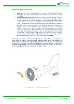
Rotor Blade Assembly - Take the five rotor blades and rotor hub plate. Be careful when
handling the blades, they may have sharp edges. Use a 10 mm socket & hexagon key and
three M6 x 16 mm Cap Heads to attach each blade to the hub plate - see Fig-5. Ensure that
the cap head end of the screw is on the inside of the blades (thus allowing the washers and
nuts to locate on rotor hub plate side). The blades should all be fixed to the hub plate on
the same side, with the blades in the same orientation. It is important that a washer is
used underneath the anti-vibration nuts. Three set-screws, three washers and three
anti-vibration nuts should be used on each blade. Tighten the fixings until the blades are
safely secured. Do not over-tighten the nuts as this may damage the blades and fixings.
Fig-5: Attaching the 5 rotor blades to the hub plate
4)
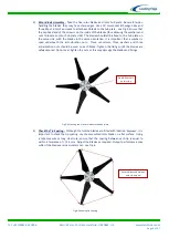
Check the Tip Spacing - Although the turbine blades are fitted with location 'keyways', it is
important to check the tip spacing. Lay the assembled rotor blade on a flat surface. Using
a tape measure or long steel rule, ensure that the spacing between each tip is equal to
within a tolerance of +/-1.5 mm. Adjust the blades as required. Output performance may
suffer if the blades are inaccurately set - see Fig-6.
Fig-6: Checking tip spacing
Ensure distance between
each tip is equal
Nuts & Washers
on this side
Summary of Contents for GA-LETU-016
Page 47: ......

