background image


Tel: +44 (0) 1981 241668 

Skyrrid Farm, Pontrilas, Hereford. HR2 0BW. UK 

           www.leadingedgepower.com  


Rev K

 Page 11 of 30


Electrical Installation 

 
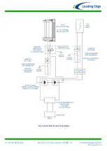
Please  refer  to  Figs  4  for  appropriate  generic  wiring  diagrams.  In  a  battery  charging  renewable 
energy  system  there  may  be  different  ways  of  wiring  small  wind  turbines,  photovoltaic  panels, 

charge  controllers  and  batteries  together.  This  type  of  system  will  often  expand  ‘organically’,  but 

the following guidelines should be followed: 


Follow  the  appropriate  electrical  code  - 

The  electrical  wiring  of  your 

LE-v50

  turbine  and 

associated electrical systems must be done in accordance with national and local electrical 
codes and regulations.  


Do not connect the turbine or batteries during the installation -

 Ensure that the turbine is 

not  running  or  connected  to  the  batteries  during  the  installation  or  wiring  process. 
Connect the output cables of the turbine together to prevent the rotor from starting up.  


Galvanic  corrosion  of  electrical  joints  -

  Try  to  avoid  connections  between  dissimilar 

metals.  For  example,  connecting  copper  and  aluminium  together  will  result  in  galvanic 
corrosion of the connection.  This  will increase the  electrical  resistance of the connection 
(wasting energy), and reduce the mechanical integrity of the joint. Where possible, use a 
fluxed solder to make electrical joints. 


Protect  the  cables  -

  The  power  transmission  cables  must  be  protected  from  mechanical 

damage and fatigue. Run the cables through an approved conduit / trunking. 


Cable  strain  relief  -

  Prevent  mechanical  strain  on  the  transmission  cables  running  down 

the tower from the turbine. Clip the cables to the inside of the tower. Failure to do this will 
result in excessive mechanical strain on the cable joints within the slip-ring assembly and 
may cause a failure. Cable ties or cable glands are a good way to prevent mechanical strain 
on the cables. 


‘Earth’

  the  System  -

  The  turbine  tower  should  have  its  own  separate  earth  point.  The 

negative  terminal  of  the  battery  bank  should  also  be  earthed.  This  provides  protection 
against the build-up of static and lightning strikes. The tower should be earthed separately 
with  its  own  ground  rod  if  there  is  a  long  transmission  distance  between  the  tower  and 
batteries. An appropriate surge arrestor could also be used to help prevent damage to the 
battery charging  system during a  lightning strike. Ensure that the earth cables are of the 
same rating as the positive and negative cables. 


Cable Selection -

 The cable size table should be used to select the minimum sized cable for 

a given transmission distance. Voltage drop in the cable will be improved if a larger cable is 
used.  


Fuses  -

  The  turbine  and  charging  circuit  should  be  protected  with  a  sui

tably  rated  ‘slow

-

blow’ DC fuse or DC circuit breaker. Please refer to the table below for the correct rating. 

The  fuse  or  breaker  should  be  positioned  between  the  turbine  and  batteries  (on  the 
positive  cable).  If  a  stop  switch  is  used  (recommended)  the  fuse  should  be  positioned 
between the switch and the batteries. 


LE-v50 Nominal 
Output Voltage 

DC Fuse / DC Circuit Breaker Rating 

12V 

6 Amp 

24V 

3 Amp 

48V 

1.5 Amp 

Summary of Contents for GA-LETU

Page 1: ...ontrilas Hereford HR2 0BW UK www leadingedgepower com Rev K Page 1 of 30 LE v50 LE v50 Extreme Turbine Installation Operation Guide A micro vertical axis turbine for trickle charging and low power app...

Page 2: ...s first 3 Introduction 4 Safety Precautions 5 Specifications 6 Package Contents 7 Tools Required For Assembly 7 Mechanical Assembly Procedure 8 Electrical Installation 11 Turbine Operation 16 Maintena...

Page 3: ...ne to run without being connected to the battery Failing to do so will result in the turbine freewheeling causing premature wear and tear and unnatural blade noise 3 On arrival ensure the main rotor i...

Page 4: ...perating life The LE v50 has been designed to be simple economic durable and yield excellent performance Specific LE v50 turbine features Innovatively designed axial flux alternator using neodymium ir...

Page 5: ...ld be completed at ground level Ensure that the batteries are disconnected during the installation procedure Twist the turbine output cables together to create a short circuit during the mechanical in...

Page 6: ...bine Name LE v50 Part Number GA LETU 010A Turbine Name LE v50 Extreme Part Number GA LETU 020A Rotor Diameter 270 mm Rated Wind Velocity 8 m s Nominal Voltage 12 24V 48V DC Rated Output 12 Watts Cut i...

Page 7: ...ler immediately Tools Required For Assembly You will require the following tools to assemble your LE v50 turbine 13 mm A F spanner 13 mm ratchet one of each required 8mm A F spanner or ratchet A set o...

Page 8: ...e will rotate freely E Retighten the upper and lower stub shaft fixings and check that the turbine still rotates freely F Reposition and fix the cowlings ensuring that they do not rub upon each other...

Page 9: ...om the baseboard it can now be fitted in its intended position The cables should come out of the bottom of the turbine when mounted The LE v50 is supplied as standard with two universal flat mounting...

Page 10: ...ficiency and cost in mind as it is unlikely that your turbine will be running at full capacity 100 of the time If in doubt consult your local electrical supplier The cable should be installed in accor...

Page 11: ...approved conduit trunking Cable strain relief Prevent mechanical strain on the transmission cables running down the tower from the turbine Clip the cables to the inside of the tower Failure to do this...

Page 12: ...Normally the LE v50 turbine does not require any external charge control equipment to be installed in the system Due to the low Tip Speed Ratio of the turbine the turbine output decreases naturally a...

Page 13: ...eford HR2 0BW UK www leadingedgepower com Rev K Page 13 of 30 Fig 4 Simple Stand Alone battery charging wiring diagram LE v50 Turbine Battery Bank wired to the appropriate voltage and capacity VE Tran...

Page 14: ...Tel 44 0 1981 241668 Skyrrid Farm Pontrilas Hereford HR2 0BW UK www leadingedgepower com Rev K Page 14 of 30 Fig 5 Stand Alone battery charging requiring DL 300 controller...

Page 15: ...Tel 44 0 1981 241668 Skyrrid Farm Pontrilas Hereford HR2 0BW UK www leadingedgepower com Rev K Page 15 of 30 Fig 5 Typical Hybrid wind solar system...

Page 16: ...the rotor speed increases so too will the current and voltage Shut Down If Run Stop switch is fitted A run stop switch is not required with the LE v50 turbine but one can be installed if desired see...

Page 17: ...mance If many dents have occurred along the edges of the blades a new set of rotor blades should be fitted part numbers available in the Spares section Remove any build up of dirt and debris from the...

Page 18: ...bine Please contact your nearest Leading Edge Turbines Dealer and quote the part numbers listed below Rotor Blade DP LETU 145 Rotor Bearing Housing DP LETU 198 Bearing Service Kit OS 296 Stator 48VDC...

Page 19: ...e warranty and may compromise the safety of the machine What is not covered by your warranty Damage caused by unsatisfactory installation of the turbine tower and or control equipment Damage caused by...

Page 20: ...nderside of the chassis Disclaimer All specifications are subject to change without prior notice The information given in this user manual is believed to be accurate and reliable Leading Edge Turbines...

Page 21: ...Tel 44 0 1981 241668 Skyrrid Farm Pontrilas Hereford HR2 0BW UK www leadingedgepower com Rev K Page 21 of 30...

Page 22: ...Tel 44 0 1981 241668 Skyrrid Farm Pontrilas Hereford HR2 0BW UK www leadingedgepower com Rev K Page 22 of 30 Appendix 1 DL 300 Charge Controller User Manual...

Page 23: ...plied to the battery and also in relation to the state of charge of the battery The DL 300 Features PWM Pulse Width Modulation for highest charging performance without flicker Selectable three stage c...

Page 24: ...re that the correct size of cable has been selected If a cable of insufficient cross sectional area is used at any point in the electrical system heat will build up in the cables causing a potential f...

Page 25: ...jumper be applied to pins 2 1 position shown to help locate pins 2 2 Use the correct voltage controller A 12V DL 300 controller should only be used on a 12V battery system A 24V DL 300 controller shou...

Page 26: ...he DL 300 and batteries on the positive cable DL 300 Voltage Set Points Whilst operating the DL 300 does a multi stage charge based on time and the bulk and float voltages 12V Set points Mode Flooded...

Page 27: ...Tel 44 0 1981 241668 Skyrrid Farm Pontrilas Hereford HR2 0BW UK www leadingedgepower com Rev K Page 27 of 30 Appendix 2 Run Stop Switch User Manual Only operate in light winds...

Page 28: ...y rotate very slowly Position 2 Turbine Run position The turbine output is allowed to flow straight through the switch Safety Precautions Safety must always be your primary concern during the assembly...

Page 29: ...Universal Run Stop switch is correctly wired as per these instructions and wiring schematics Incorrect wiring may lead to a short circuit being placed across the batteries which can lead to fire or ex...

Page 30: ...s Hereford HR2 0BW UK www leadingedgepower com Rev K Page 30 of 30 Contact Us Your Local Distributor Leading Edge Turbines Ltd Skyrrid Farm Pontrilas Hereford HR2 0BW UK Tel 44 0 1981 241 668 info lea...

Reviews: