Tel: +44 (0) 1981 241668
Skyrrid Farm, Pontrilas, Hereford. HR2 0BW. UK
www.leadingedgepower.com
Rev K
Page 28 of 30
Introduction
Please read this manual thoroughly before attempting to assemble, install or operate your
Universal Run / Stop Switch. This will assure optimum performance and safety.
The Universal Run / Stop Switch is designed to allow the user to dynamically brake an
LE-300
turbine at will. This is achieved by disconnecting the power output of the turbine from the relevant
load and diverting it to a short circuit which then applies the dynamic braking effect on the
permanent magnet alternator of the turbine. This will bring the turbine to a near stop for
maintenance only.
The Universal Run / Stop Switch can be used with turbines of different manufacture as long as the
relevant turbine has the following characteristics:
3-Phase Wild AC not exceeding 500 V & 16 A
Wild DC not exceeding 150 V & 10 A
Mechanically and electrically capable of dynamic braking
Operation & Specification
The Universal Run / Stop Switch should be operated during low speeds as repeated use at high
speeds may cause damage if the turbine head (it was not designed to withstand repeated dynamic
braking operations).
The switch has two positions:
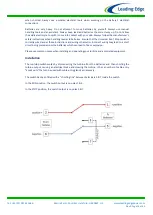
Position 1: Turbine 'Stop' position. The turbine is dynamically braked and may rotate very slowly.
Position 2: Turbine 'Run' position. The turbine output is allowed to flow straight through the switch.
Safety Precautions
Safety must always be your primary concern during the assembly, installation and operation of your
turbine and other associated equipment. Always be aware of the risks involved with mechanical
and electrical installation work. If in doubt about any issue regarding your turbine system, please
seek further assistance before proceeding.
Mechanical Safety Hazards:
Whilst installing the Universal Run / Stop Switch, ensure that the turbine is suitably restrained and
not allowed to operate during the installation.
Electrical Safety Hazards:
Caution should always be used when connecting the
LE-v50
or other equipment to the electrical
system.
Ensure that you have followed the cable-sizing guidelines to ensure that the correct size of cable
has been selected. If a cable of insufficient cross-sectional area is used at any point in the electrical
system, heat will build up in the cables causing a potential fire hazard. A properly-sized fuse or
circuit breaker should be used in the cables connected to the battery. This will stop the risk of short
circuit currents.
Batteries used in renewable energy systems can deliver a serious amount of current. A short circuit
in the battery circuit can lead to hundreds of Amps flowing through the battery cables. This will
cause a heat build-up and ultimately an electrical fire. Batteries are also susceptible to exploding


