Tel: +44 (0) 1981 241668
Skyrrid Farm, Pontrilas, Hereford. HR2 0BW. UK
www.leadingedgepower.com
Rev K
Page 8 of 30
Mechanical Assembly Procedure
1)
Unpacking -
Inspect the contents of the box and ensure that all items are present and free
from damage. If any of the components are missing or damaged, please contact your
dealer immediately.
2)
Check Main Rotor & Continuity -
Ensure that the main rotor is free turning and does not
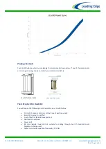
scrape or rub as it rotates - see Fig 4. As the turbine is shipped in a horizontal orientation,
it may be the case that the upper or lower stub shafts or cowlings have shifted during
transit.
If the turbine blades feel stiff and do not rotate freely, follow the below steps to reset the
stub shaft positions:
A)
Remove the M5 cowling fixings and then the cowlings themselves.
B)
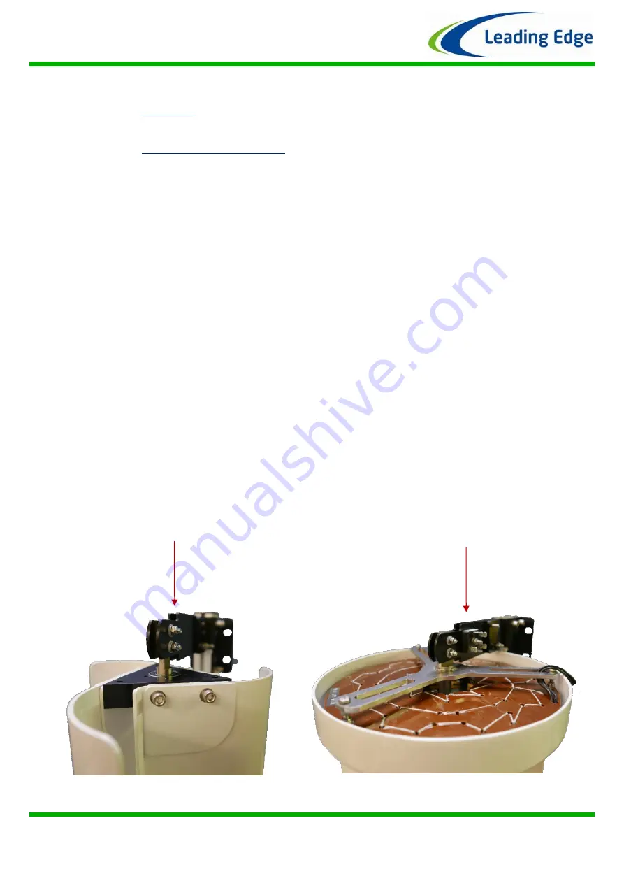
Slightly slacken the M5 fixings on the upper and lower stub shafts.
C)
Hold the turbine
vertically
and rotate the main rotor blades.
D)
The stub shafts will now reposition themselves and the turbine will rotate freely.
E)
Retighten the upper and lower stub shaft fixings and check that the turbine still
rotates freely.
F)
Reposition and fix the cowlings ensuring that they do not rub upon each other..
The bearing units used in the magnet rotor assembly are factory lubricated and sealed for
life. It will take approximately 100 hours of normal operation for the seals to ‘bed
-
in’ and
the lubrication to be distributed correctly around the bearing raceways and ball cages.
During this period you may notice a reduced performance caused by the additional friction
of the bearing seals. In operating temperatures of
–
10 degrees Centigrade or lower, this
‘bedding
-
in’ period will be extended by a further 50 hours of normal o
peration.
Connect a digital multi-meter to the positive (red) and negative (black) output leads
extending from the rear of the turbine. With the multi-meter set to detect DC Volts
(0-20V), a voltage should be displayed when the main rotor is spun by hand. This voltage
will vary with the speed of rotation. If no voltage is detected whilst turning the rotor,
please contact your dealer immediately.
Fig 3: Checking voltage output
Upper Stub Shaft Fixings
Lower Stub Shaft Fixings

