background image


D

D

B

B

8

8

1

1

0

0

A

A


D

D

i

i

g

g

i

i

t

t

a

a

l

l


D

D

C

C


S

S

e

e

r

r

v

v

o

o


D

D

r

r

i

i

v

v

e

e

r

r


M

M

a

a

n

n

u

u

a

a

l

l


V

V

1

1

.

.

0

0


Tel: (86)755-26434369                                                 

3

                                                  Web site: www.leadshine.com 

Operating Environment and Parameters 

Cooling 

Natural cooling or forced cooling 

Environment 

Avoid dust, oil fog and corrosive gases 

Ambient Temperature 

º

 C  

 50 

º

 C 

Humidity 

40 

 95%RH 

Operating Environment 

Vibration 

5.9 m/s

2

 Max


Storage Temperature 

-20 

º

 C 

 +65 

º

 C 

Weight 

Approx. 130 grams (4.6 oz) 

3. Connections 

Connector Configuration 

Term. 

Pin 

Descriptions 

PUL+ 

Connect to positive pole of the pulse control signal. 

PUL- 

Connect to negative pole of the pulse control signal. 

DIR+ 

Connect to positive pole of the direction control signal. 

DIR- 

Connect to negative pole of the direction control signal. 

EB+ 

Connect to positive pole of the encoder channel B feedback signal. 

EB- 

Connect to negative pole of the encoder channel B feedback signal. 

EA+ 

Connect to positive pole of the encoder channel A feedback signal. 

EA- 

Connect to negative pole of the encoder channel A feedback signal. 

E +5V 

Positive pole of the auxiliary power supply (50 mA (Max)). 

10 

EGND 

Ground of the auxiliary power supply. 

11 

ERR/RES 

Error alarm and reset/start port. 

12 

Motor+ 

Connect to positive pole of the DC servo motor. 

13 

Motor- 

Connect to negative pole of the DC servo motor. 

14 

+18 TO 80VDC 

Connect to positive pole of the +18 TO 80VDC power supply. 

15 

PGND 

Connect to ground of the +18 TO 80VDC power supply. 


D

D

B

B

8

8

1

1

0

0

A

A


D

D

i

i

g

g

i

i

t

t

a

a

l

l


D

D

C

C


S

S

e

e

r

r

v

v

o

o


D

D

r

r

i

i

v

v

e

e

r

r


M

M

a

a

n

n

u

u

a

a

l

l


V

V

1

1

.

.

0

0


Tel: (86)755-26434369                                                 

4

                                                  Web site: www.leadshine.com 

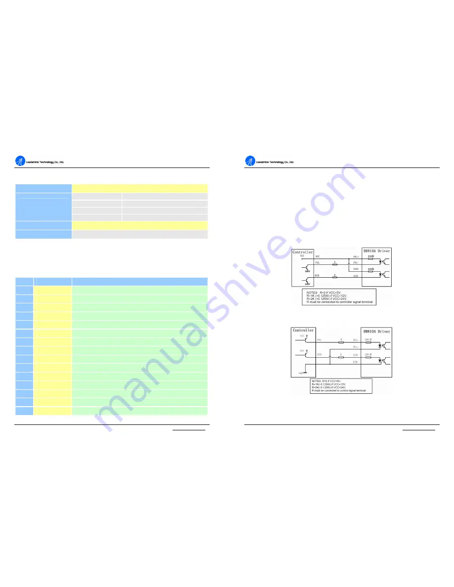
Control Signal Connections 

The  DB810A  can  accept  differential  and  single-ended  inputs  (including 
open-collector and PNP output). The DB810A have 2 optically isolated logic inputs 
to  accept  line  driver  control  signals.  These  inputs  are  isolated  to  minimize  or 
eliminate  electrical  noises coupled  onto  the  drive control  signals.  Recommend  use 
line driver control signals to increase noise immunity in interference environments. 
In  the  following  figures,  connections  to  open-collector  and  differential  control 
signals are illustrated. 


Figure 2: Connections to open-collector control signal (common-anode) 


Figure 3: Connections to PNP signal (common-cathode) 

Summary of Contents for DB810A

Page 1: ...to any products herein to improve reliability function or design Leadshine does not assume any liability arising out of the application or use of any product or circuit described herein neither does it convey any license under its patent rights of others Leadshine s general policy does not recommend the use of its products in life support or aircraft applications wherein a failure or malfunction o...

Page 2: ...gulated Power Supply 8 Selecting Supply Voltage 8 Prepare Controller 8 Initialize the DB810A 9 System Connections and Noise Prevention 9 Wire Gauge 10 Cable Routing 10 Twisted Wires 10 Cable Shielding 10 System Grounding 11 Contents Tel 86 755 26434369 II Web site www leadshine com Power Supply Connection 11 5 Tuning the servo 12 Testing the servo 12 Tuning the Servo 12 Adjusting Gain and Damp Coe...

Page 3: ...far lower than those of AC servo drivers Features l 18 80VDC 0 20A 20 400W l PID feedback servo drive l Feedback resolution 4 encoder line count l Lock range 128 count following error l Opto isolated pulse and direction inputs differential l Over current and short circuit protection l Small size Applications Suitable for a wide range of equipments and instruments such as mini type engraving machin...

Page 4: ...nel A feedback signal 9 E 5V Positive pole of the auxiliary power supply 50 mA Max 10 EGND Ground of the auxiliary power supply 11 ERR RES Error alarm and reset start port 12 Motor Connect to positive pole of the DC servo motor 13 Motor Connect to negative pole of the DC servo motor 14 18 TO 80VDC Connect to positive pole of the 18 TO 80VDC power supply 15 PGND Connect to ground of the 18 TO 80VDC...

Page 5: ... 50mA the DB810A can supply the encoder directly and connect it as Figure 5 or Figure 6 If the encoder drains more than 50mA use an external DC supply and connect it as Figure 7 or Figure 8 Figure 5 The DB810A supplies the Figure 6 The DB810A supplies the differential encoder directly single ended encoder directly D DB B8 81 10 0A A D Di ig gi it ta al l D DC C S Se er rv vo o D Dr ri iv ve er r M...

Page 6: ...d current surge If regulated power supplies such as most switching supplies are indeed used it is important to have large current output rating to avoid problems like current clamp for example using 4A supply for 3A motor driver operation On the other hand if unregulated supply is used one may use a power supply of lower current rating than that of motor typically 50 70 of motor current The reason...

Page 7: ... 10 Web site www leadshine com Wire Gauge The smaller wire diameter lower gauge the higher impedance Higher impedance wire will broadcast more noise than lower impedance wire Therefore when selecting the wire gauge it is preferable to select lower gauge i e larger diameter wire This recommendation becomes more critical as the cable length increases Use the following table to select the appropriate...

Page 8: ...source of noise When the power supply lines are longer than 50 cm a 1000µF 100V electrolytic capacitor should be connected between the terminal PGND and the terminal 18 TO 80VDC This capacitor stabilizes the voltage supplied to the drive as well as filters noise on the power supply line Please note that the polarity D DB B8 81 10 0A A D Di ig gi it ta al l D DC C S Se er rv vo o D Dr ri iv ve er r...

Page 9: ... find it s much easier than investigating its step response The easiest way to get a tracking error or position following error response is to induce an impulse load on the motor See Figure 12 at time 20 And for evaluating servo performances a test point including TEST point and GND point is set inside of the DB810A See Figure 14 When there is no position error the voltage should be 2 5V The volta...

Page 10: ... to stabilize the system After increasing Damp or decreasing Gain we got an impulse response shown as Figure 15 This is UNDER DAMPED response The system has a slightly oscillatory response causing a longer settling time about 34 5ms This oscillatory response is a cause of motor ringing too Although the steady state position error of the DB810A servo system is usually can be eliminated to 1 count s...

Page 11: ... 13 30ms much faster than that of Figure 15 b When you get a CRITICALLY DAMPED response you can stop tuning the servo a Max error b Steady state error Figure 17 CRITICALLY DAMPED response However if you increase Damp or decrease Gain too much you may get an OVER DAMPED response like Figure 18 In this situation the motor returns to SETTLING BAND with a long SETTLING TIME In Figure 18 b the SETTLING...

Page 12: ... 20 Web site www leadshine com 6 Using Tips Current Limit Setting The current Limit potentiometer is adjustable from 0 A to 20 A Normally the Limit potentiometer is set to Maximum Subtransient Current of the motor default setting is 20 A unless you want to limit motor torque to a lower value When the torque demand due to load doesn t exceeds current Limit setting motor speed and position are unaff...

Page 13: ...the CW direction when the direction input is high logical 1 If instead CCW is preferred then 1 Reverse the motor and motor leads 2 Reverse the encoder Channel A and Channel B leads ERR RES Port This port functions as an error output and as a servo start restart input When first testing the DB810A or it is not necessary to read the state of the error output ERR RES port can be connected to E 5V por...

Page 14: ...shine for warranty service and Leadshine shall pay for return of products to customer WARRANTY LIMITATIONS Leadshine makes no other warranty either expressed or implied with respect to the product Leadshine specifically disclaims the implied warranties of merchantability and fitness for a particular purpose Some jurisdictions do not allow limitations on how long and implied warranty lasts so the a...

Reviews: