background image

DMA860H Fully Digital Stepper Drive Manual V1.0

2

Pulse Voltage

-

5

-

VDC

Isolation resistance

500

Operating Environment and other Specifications

Cooling

Natural Cooling or Forced cooling

Operating Environment

Environment

Avoid dust, oil fog and corrosive gases

Ambient Temperature

0

℃ -

50

Humidity

40%RH

90%RH

Operating Temperature

70

Max

Vibration

5.9m/s

2

Max

Storage Temperature

-20

℃ -

65

Weight

Approx. 620g (21.9oz)

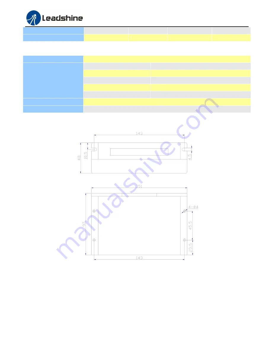
Mechanical Specifications

Figure 1: Mechanical specifications

*Recommend use side mounting for better heat dissipation

Elimination of Heat

Driver’s reliable working temperature should be <70

(158

), and motor working temperature should be

<80

(176

);

It is recommended to use automatic idle-current mode, namely current automatically reduce to 50% when motor
stops, so as to reduce driver heating and motor heating;

It is recommended to mount the driver vertically to maximize heat sink area. Use forced cooling method to cool

Summary of Contents for DMA860H

Page 1: ... Attention Please read this manual carefully before using the drive 3 F Block 2 Nanyou Tianan Industrial Park Nanshan Dist Shenzhen China T 86 755 26409254 F 86 755 26402718 Web site www leadshine com E Mail sales leadshine com 2012 by Leadshine Technology Company Limited All Rights Reserved ...

Page 2: ... does it convey any license under its patent rights of others Leadshine s general policy does not recommend the use of its products in life support or aircraft applications wherein a failure or malfunction of the product may directly threaten life or injury According to Leadshine s terms and conditions of sales the user of Leadshine s products in life support or aircraft applications assumes all r...

Page 3: ...tions to 6 lead Motors 5 Half Coil Configurations 5 Full Coil Configurations 5 Connections to 8 lead Motors 5 Series Connections 6 Parallel Connections 6 6 Power Supply Selection 6 Regulated or Unregulated Power Supply 6 Multiple Drivers 7 Selecting Supply Voltage 7 7 Selecting Microstep Resolution and Driver Output Current 7 Microstep Resolution Selection 7 Current Settings 8 Dynamic Current Sett...

Page 4: ...DMA860H Fully Digital Stepper Drive Manual V1 0 II Warranty Limitations 13 Contact Us 13 ...

Page 5: ... a higher microstep output thus offers smoother motor movement 16 selectable microstep resolutions including 400 800 1600 3200 6400 12800 25600 51200 1000 2000 4000 5000 8000 10000 20000 40000 Soft start with no jump when powered on Input voltage 18 80VAC or 26 113VDC 8 selectable peak current including 2 40A 3 08A 3 77A 4 45A 5 14A 5 83A 6 52A 7 20A Pulse input frequency up to 200 KHz TTL compati...

Page 6: ...torage Temperature 20 65 Weight Approx 620g 21 9oz Mechanical Specifications Figure 1 Mechanical specifications Recommend use side mounting for better heat dissipation Elimination of Heat Driver s reliable working temperature should be 70 158 and motor working temperature should be 80 176 It is recommended to use automatic idle current mode namely current automatically reduce to 50 when motor stop...

Page 7: ...ld be ahead of PUL signal by 5μs at least 4 5 5V when DIR HIGH 0 0 5V when DIR LOW Please note that rotation direction is also related to motor driver wiring match Exchanging the connection of two wires for a coil to the driver will reverse motion direction DIR ENA Enable signal This signal is used for enabling disabling the driver High level NPN control signal PNP and differential control signals...

Page 8: ...ol signals Recommend use line driver control signals to increase noise immunity of the driver in interference environments In the following figures connections to open collector and PNP signals are illustrated Figure 3 Connections to open collector Figure 4 Connection to PNP signal common cathode signal common anode 5 Connecting the Motor The DMA860H can drive any 2 pahse and 4 pahse hybrid steppi...

Page 9: ...ut will be more stable at higher speeds This configuration is also referred to as half chopper In setting the driver output current multiply the specified per phase or unipolar current rating by 1 4 to determine the peak output current Figure 6 6 lead motor half coil higher speed connections Full Coil Configurations The full coil configuration on a six lead motor should be used in applications whe...

Page 10: ...e determines the high speed performance of the motor while output current determines the output torque of the driven motor particularly at lower speed Higher supply voltage will allow higher motor speed to be achieved at the price of more noise and heating If the motion speed requirement is low it s better to use lower supply voltage to decrease noise heating and improve reliability Regulated or U...

Page 11: ...ection or even driver damage Therefore it is suggested to choose only sufficiently high supply voltage for intended applications and it is suggested to use power supplies with theoretical output voltage of 20 68VDC leaving room for power fluctuation and back EMF 7 Selecting Microstep Resolution and Driver Output Current This driver uses an 8 bit DIP switch to set microstep resolution and motor ope...

Page 12: ...8A 5 14A ON ON OFF 4 86A 5 83A OFF ON OFF 5 43A 6 52A ON OFF OFF 6 00A 7 20A OFF OFF OFF Notes Due to motor inductance the actual current in the coil may be smaller than the dynamic current setting particularly under high speed condition Standstill Current Setting SW4 is used for this purpose OFF meaning that the standstill current is set to be half of the selected dynamic current and ON meaning t...

Page 13: ... at least 10 cm otherwise the disturbing signals generated by motor will easily disturb pulse direction signals causing motor position error system instability and other failures If a power supply serves several drivers separately connecting the drivers is recommended instead of daisy chaining It is prohibited to pull and plug connector P2 while the driver is powered ON because there is high curre...

Page 14: ...able DIR ENA AC AC Recommended Power Supply 20 72VAC VCC 5V A A B B Stepper Motor Figure 10 Typical connection 10 Sequence Chart of Control Signals In order to avoid some fault operations and deviations PUL DIR and ENA should abide by some rules shown as following diagram Figure 11 Sequence chart of control signals Remark ...

Page 15: ...function properly after removing above problems 12 Frequently Asked Questions In the event that your driver doesn t operate properly the first step is to identify whether the problem is electrical or mechanical in nature The next step is to isolate the system component that is causing the problem As part of this process you may have to disconnect the individual components that make up your system ...

Page 16: ...eadshine Technology Co Ltd warrants its products against defects in materials and workmanship for a period of 12 months from shipment out of factory During the warranty period Leadshine will either at its option repair or replace products which proved to be defective Exclusions The above warranty does not extend to any product damaged by reasons of improper or inadequate handlings by customer impr...

Page 17: ...dshine com to obtain a returned material authorization number RMA before returning product for service Please include a written description of the problem along with contact name and address Send failed product to distributor in your area or Leadshine Technology Co Ltd 3 F Block 2 Nanyou Tianan Industrial Park Nanshan Dist Shenzhen China Also enclose information regarding the circumstances prior t...

Page 18: ...ia 92618 Tel 1 949 608 7270 Fax 1 949 608 7298 Web http www leadshineUSA com Email sales leadshineUSA com and support leadshineUSA com Leadshine Hong Kong Address Rm 3 9 F Block E Wah Lok Industrial Center 31 41 Shan Mei St Fo Tan Shatin Hong Kong Tel 852 2952 9114 Fax 852 2952 9395 Email hk_sales leadshine com ...

Reviews: