Hardware Manual for the DMC5400 Motion Controller
Tel: +086 0755-26434369 Email: sales@leadshine.com Web Site: www.leadshine.com
Page: 14/36
4.3 Slow Down Signal SD
The slow down signals (SD0~SD3) are used as input signals for slowing down the speed to the initial speed when
necessary. The following table lists the relative signal name, pin number, and the axis number.
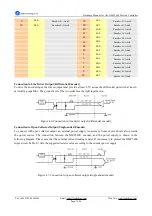
Table 4-3: SD pins
X1 Pin
Signal
Description (Axis)
X2 Pin
Signal
Description (Axis)
37
SD0
Slow down signal, Axis0
28
SD3
Slow down signal, Axis3
29
SD1
Slow down signal, Axis1
63
SD2
Slow down signal, Axis2
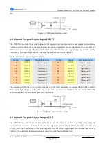
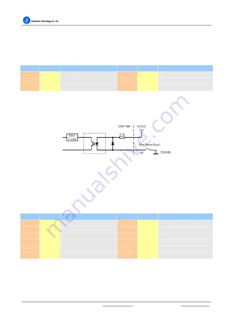
The input circuits of the SD signals are shown as Figure 4.3. Usually, a switch is used to indicate the position
where slowing down is necessary. The specifications of the switches should with contact capacity of +24V, 6mA
minimum. An internal filter circuit is used to filter out the high frequency spike, which may cause wrong
operation. See
“
Software Manual for the DMC5400 Motion Controller
”
for more detail operation of the SD.
Figure4.3: SD signal interface circuit
4.4 End Limit Signal EL+ & EL-
There are two end-limit signals EL+ and EL- for each axis. EL+ indicates end limit signal in positive direction and
EL- indicates end limit signal in minus direction. The relative signal name, pin number and axis number are
shown in the following table.
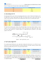
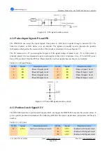
Table 4-4: EL pins
X1 Pin
Signal
Description (Axis)
X2 Pin
Signal
Description (Axis)
35
EL0+
Positive end-limit signal, Axis0
26
EL3+
Positive end-limit signal, Axis3
36
EL0-
Minus end-limit signal, Axis0
27
EL3-
Minus end-limit signal, Axis3
27
EL1+
Positive end-limit signal, Axis1
28
EL1-
Minus end-limit signal, Axis1
61
EL2+
Positive end-limit signal, Axis2
62
EL2-
Minus end-limit signal, Axis2
The switch S1 is used to set the types of EL limit switches, see Table 4-5. The default setting of EL switch type is
“
normal open
”
type limit switch. The switch OFF is to use the
“
normal closed
”
type limit switch. The default
setting is set as normal open type.


