Hardware Manual for the DMC5400 Motion Controller
Tel: +086 0755-26434369 Email: sales@leadshine.com Web Site: www.leadshine.com
Page: 16/36
9
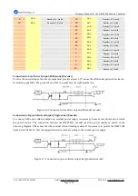
EZ0+
Encoder Z+, Axis0
19
EZ1+
Encoder Z+, Axis0
10
EZ0-
Encoder Z-, Axis0
20
EZ1-
Encoder Z-, Axis0
40
EA2+
Encoder A+, Axis0
41
EA2-
Encoder A-, Axis0
42
EB2+
Encoder B+, Axis0
43
EB2-
Encoder B-, Axis0
44
EZ2+
Encoder Z+, Axis0
45
EZ2-
Encoder Z-, Axis0
5
EA3+
Encoder A+, Axis0
6
EA3-
Encoder A-, Axis0
7
EB3+
Encoder B+, Axis0
8
EB3-
Encoder B-, Axis0
9
EZ3+
Encoder Z+, Axis0
10
EZ3-
Encoder Z-, Axis0
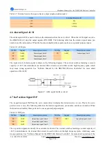
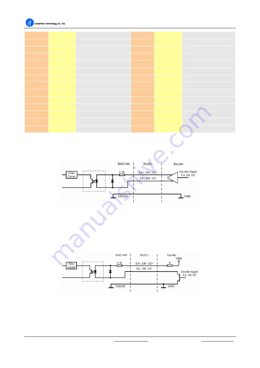
Connection to Line Driver Output (Differential Encoder)
To drive the encoder input, the driver output must provide at least 3.5V across the differential pairs with at least 6
mA driving capability. The ground level of the two sides must be tight together too.
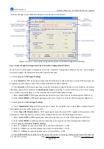
Figure 4.6: Connection to line driver output (differential encoder)
Connection to Open Collector Output (Single-ended Encoder)
To connect with open collector output, an external power supply is necessary. Some motor drivers also provide
the power source. The connection between the DMC5400, encoder, and the power supply is shown in the
following diagram. Please note that the external current limiting resistor R is necessary to protect the DMC5400
input circuit. Table 4-7 lists the suggested resistor value according to the encoder power supply.
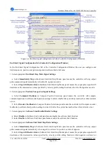
Figure 4.7: Connection to open collector output (single-ended encoder)


