EM522-CAN Field bus Stepper Drive User Manual V1.0
13
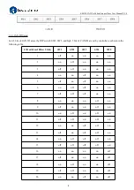
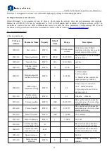
2073+00
Motor
auto-running when
power on
R/W/S
0
0/1
0: Motor normal standby when
power on
1: Motor turns 30°and reverse
30 when power on, then
standby
2150+00
CAN ID high 2 bit
R/W/S
0
0~3
Slave station address:
Activate after repower
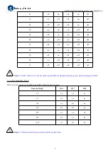
2151+00
CANopen baud
rate
R/W/S
0
0~7
0:1000kBit/sec
1:Invalid
2:500 kBit/sec
3:250 kBit/sec
4:125 kBit/sec
5:100 kBit/sec
6:50 kBit/sec
7:20 kBit/sec
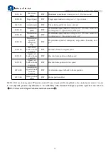
2152+01
Digital input
IN1 function
selection
R/W/S
1
0~32768
1:Home signal
2:Positive limit
4:Negative limit
32768:Emergency stop
2152+02
Digital input
IN2 function
selection
R/W/S
2
0~32768
1:Home signal
2:Positive limit
4:Negative limit
32768:Emergency stop
2152+03
Digital input
IN3 function
selection
R/W/S
4
0~32768
1:Home signal
2:Positive limit
4:Negative limit
32768:Emergency stop
2153+01
Digital input
IN1 filter time
R/W/S
1000
50~60000
unit: us
2153+02
Digital input
IN2 filter time
R/W/S
1000
50~60000
unit: us
2153+03
Digital input
IN3 filter time
R/W/S
1000
50~60000
unit: us
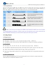
2154+00
Level polarity of
digital inputs
IN1,IN2,IN3
R/W/S
0
0~7
0:Low level Optocoupler has no
input, port is in free status;
Optocoupler has no input , port
is in trigger status
1: High level Optocoupler has
no input, port is in trigger
status; Optocoupler has no
input , port is in free status
bit0: IN1 polarity setting;
bit1: IN2 polarity setting;
bit2: IN3 polarity setting.
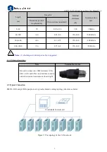
2155+00
Digital input
IN1,IN2,IN3 level
R/W/S
0
0~7
Read input IO port polarity Low
3 bits corresponding external 3
input IO port
0:Three digital input
IN1,IN2,IN3 are low level
7:Three digital input
IN1,IN2,IN3 are high level

