iEM-RS Series Modbus RS485 Integrated Stepper Motor
32
paths
paths
Pr9.56- Pr9.63
Similar as above
paths
Similar as above
paths
PR path 7
Pr9.64- Pr9.71
Similar as above
paths
Similar as above
paths
PR path 8
5.4.2 PR Path Configuration
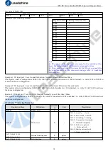
If use the digital input ports to configure the PR path, they can be set to ADD0, ADD1, ADD2 and ADD3, thus forming
16-segment PR path, and then trigger the path number to complete the PR motion.
Each digital input of the drive can be configured as any one of ADD0 - ADD3, then combine the path numbers, as shown in the
table below,
“on” means the digital input is configured as ADDx (x=1-3), and the input signal optocoupler on , “off “ means
signal input off.
PR path
DI1
(ADD0)
DI2
(ADD1)
DI3
(ADD2)
DI4
(ADD3)
DI5
(CTRG)
Path 0
off
off
off
off
on
Path 1
on
off
off
off
on
Path 2
off
on
off
off
on
Path 3
on
on
off
off
on
Path 4
off
off
on
off
on
Path 5
on
off
on
off
on
Path 6
off
on
on
off
on
Path 7
on
on
on
off
on
Path 8
off
off
off
on
on
Path 9
on
off
off
on
on
Path 10
off
on
off
on
on
Path 11
on
on
off
on
on
Path 12
off
off
on
on
on
Path 13
on
off
on
on
on
Path 14
off
on
on
on
on
Path 15
on
on
on
on
on
Note: The 4 digital inputs do not have to be configured as ADD0 - ADD3, it is configured according to the actual required path
motions. For example, if only Path0 is needed, refer to the above table, DI1-4 are not required to be configured as ADD0 -
ADD3, because they are are “off”, only one input needs to be configured as CTRG.
5.4.3 Other functions of PR
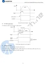
Timing sequence of signal path

