CS-D508 Closed-loop Stepper Drive User Manual
Motion Control Products Ltd. Tel.: (+44) 01202 599922
ALM+
O
Configurable Digital Output Signal: A configurable OC output signal. It takes a sinking or
sourcing 20mA current at 5-24V. It can to be configured as one of the 3 types,
ALARM
(default)
,
IN POSITION
, or
BRAKE CONTROL
through Leadshine ProTuner CS-D software.
ALM-
O
Notes:
(1) Shielding control signal wires is suggested;
(2)
To
avoid/reduce interference, do NOT tie control signal cables and power wires together.
b)
Fault Output, In Position, or Brake control Output Configuration
The digital output on the P1 connector, marked as ALM+ & ALM-, is software configurable (please refer to Leadshine
ProTuner CS-D software manual). It can be configured as one of the available 3 options - Fault Output”, “In Position”, and
“Brake Control”. Read Leadshine ProTuner CS-D closed loop software manual for how to configure this output.
•
Fault Output
FAULT output is the default configuration. This output signals a fault condition including over-voltage, over-current,
or position following error. This output can be used to drive devices such as a relay, a LED, etc.; or as an input signal
to electronic devices like a PLC.
For example, in a multi-axis system like a CNC machine when one of the axes fails such a fault output signal can be
feedback to the motion controller for a followed action (e.g., auto machine shutdown, auto error clearing, etc.).
•
In Position
Use Leadshine ProTuner for CS-D software to configure this output as an IN POSITION output. In this case, an output
signal can be sent out when the targeted position is in the “Target” range (see
parameter Distance to Send "In
position" Output Signal
in software manual) to external devices such as relays, motion controllers, PLCs, IO boards,
etc.
•
Brake Control
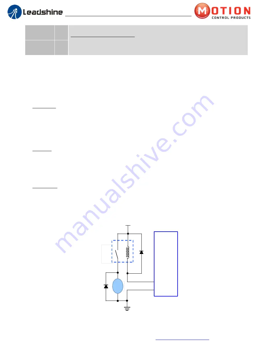
Use Leadshine ProTuner for CS-D software to configure this output as a BRAKE CONTROL output. In this case, this
signal can be used for automatic brake control while system power failure. It is recommended to connect a fly-
wheel diode in parallel to a 24VDC relay and brake coil connection. Refer to the following figure for brake
connection.
+24VDC
GND
CS-D508
ALM+
ALM-
Brake
Coil
24VDC
Relay
Figure 3: Brake Output Connection


