background image


User Manual for ELD2-CAN Servo 


    www.leadshine.com


94 

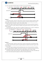
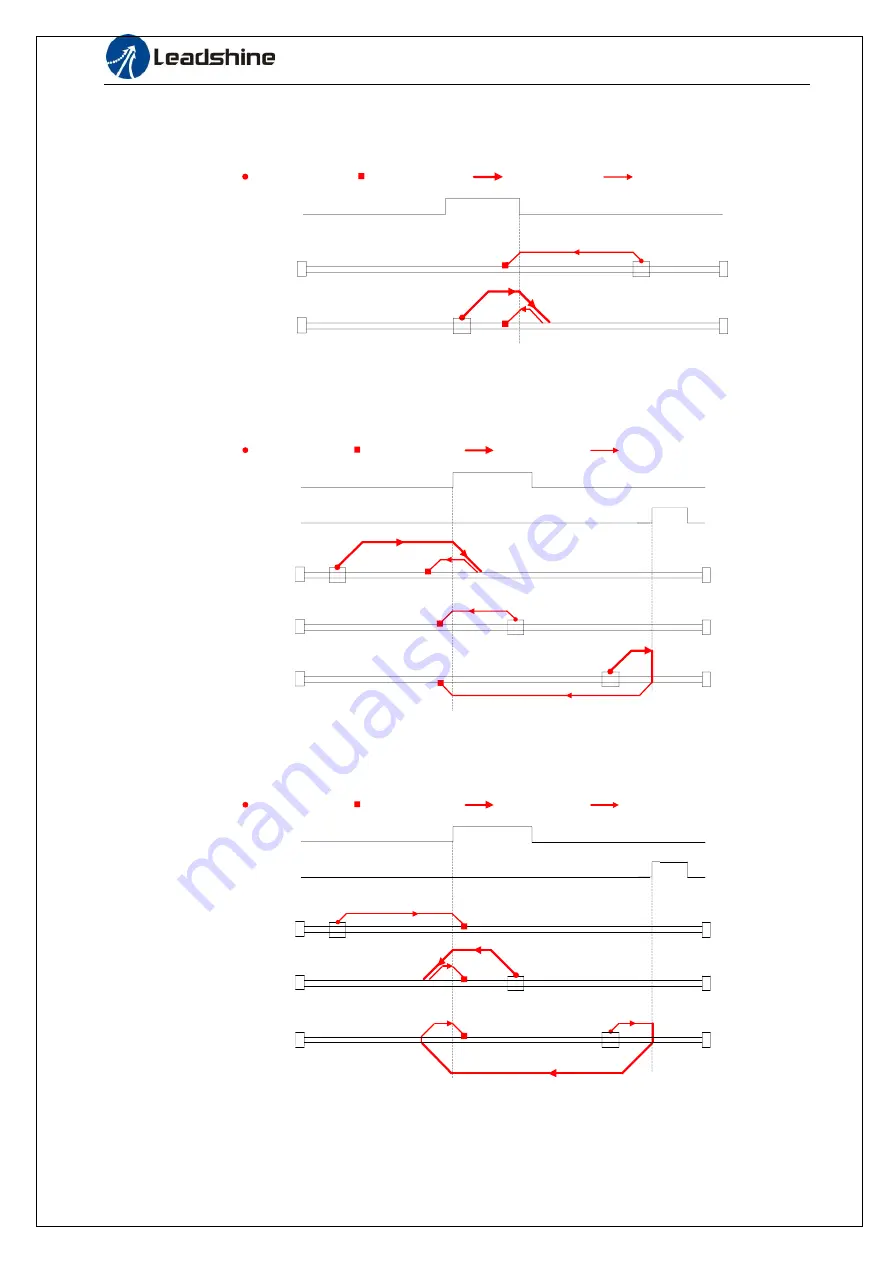
Method 22


This method is similar to method 

6

HOME-SWITCH

A

B

Start Position

Stop Position

High speed

6099h-01h

Low speed
6099h-02h


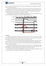
Method 23


This method is similar to method 7 

HOME-SWITCH

B

Start Position

Stop Potion

High speed

6099h-01h

Low speed
6099h-02h

POT signal

A

C


Method 24


This method is similar to method 8 

HOME-SWITCH

B

Start Position

Stop Position

High speed

6099h-01h

Low speed
6099h-02h

POT signal

A

C


Summary of Contents for ELD2-CAN70 Series

Page 1: ...User Manual for ELD2 CAN Servo www leadshine com 1 ELD2 CAN70 User Manual ...

Page 2: ...uld result in loss of life or serious injury Caution indicates that the error operation could result in operator injured also make equipment damaged Attention indicates that the error use may damage product and equipment Safety precautions Warning The design and manufacture of product doesn t use in mechanic and system which have a threat to operator The safety protection must be provided in desig...

Page 3: ...ervo drive and servo motor installed correctly After correctly connecting cables insulate the live parts with insulator Caution The wiring must be connected correctly and steadily otherwise servo motor may run incorrectly or damage the equipment We mustn t connect capacitors inductors or filters between servo motor and servo drive The wire and temperature resistant object must not be close to radi...

Page 4: ...signal before restart Keep away from machine because of restart suddenly if the drive is powered on again after momentary interruption the design of the machine should be assured to avoid danger when restart occurs System selection Attention The rate torque of servo motor should be larger than effective continuous load torque The ratio of load inertia and motor inertia should be smaller than recom...

Page 5: ...tion Port 18 3 2 4 Power Port 18 3 2 5 CAN bus connector 19 3 2 6 CAN Node ID and Baud rate switch 19 3 3 I O Interface Principle 20 3 3 1 Digital Input Output Interface 20 Chapter 4 Parameter 23 4 1 Parameter List 23 4 1 1 Drive parameters 23 4 1 2 Manufacturer parameters 26 4 1 3 Motion parameter starting with object dictionary 6000 28 4 2 Parameters Function 31 4 2 1 Class 0 Basic Setting 31 4 ...

Page 6: ...rolword in profile position mode 74 6 4 2 Statusword in profile position mode 75 6 4 3 Related objects 75 6 4 4 Example of profile position mode 76 6 5 Profile velocity mode 76 6 5 1 Controlword in profile velocity mode 76 6 5 2 Statusword in profile velocity mode 77 6 5 3 Related objects 77 6 5 4 Example of profile velocity mode 78 6 6 Profile torque mode 78 6 6 1 Controlword in profile torque mo...

Page 7: ...User Manual for ELD2 CAN Servo www leadshine com 7 Chapter 8 Product Specification 107 8 1 Drive Technical Specification 107 8 2 Accessory selection 108 Contact us 109 ...

Page 8: ...planning of bus communication servo is realized in the drive The controller only needs to transfer the target position speed acceleration and other information to the drive Therefore the drive can predict the motion parameters of the next moment in advance internally and then take feedforward measures to improve the motion performance Reduce system wiring complexity Under the pulse communication m...

Page 9: ...2 12 12 12 Control method IGBT PWM sinusoidal Wave Drive Overload 300 Brake resistor External connection Protection rank IP20 Features Drive model ELD2 CAN7010 ELD2 CAN7015 ELD2 CAN7020 ELD2 CAN7030 Modes of operation Profile Position Profile Velocity Profile Torque Command source Over the Network Inputs Outputs 7 programmable single end inputs 24V 2 programmable differential outputs 3 programmabl...

Page 10: ...um Output Power 7010 400W 7015 600W 7020 750W 7030 1200W RS RS485 Pulse Dir Analog Input Modbus CAN CANopen Low voltage AC servo drive 24 70Vdc b Servo motor type The ELD2 series AC servo drive can be matched with a variety of domestic and foreign servo motor Matched Motors Power Range Up to 1200W Motor Supported Brushless Brushed Voltage Range 24 70Vdc Feedback supported 1000 2500lines incrementa...

Page 11: ...mstance Requirement Item ELD2 series drive ELDM servo motor Temperature 0 55 25 40 Humility Under 90 RH free from condensation Under 90 RH free from condensation Atmospheric environment Indoor no exposure no corrosive gas or flammable gas no oil or dust Indoor no exposure no corrosive gas or flammable gas no oil or dust Altitude Lower than 1000m Lower than 2500m Vibration Less than 0 5G 4 9m s2 10...

Page 12: ...w leadshine com 12 Figure 2 1 A installation method of drive ELD2 CAN7010 Figure 2 1 B installation method of drive ELD2 CAN7015 ELD2 CAN7020 ELD2 CAN7030 2 2 2 Installation Space Reserve enough surrounding space for effective cooling ...

Page 13: ...ansporting it No knocking motor shaft or encoders prevent motor by vibration or shock The motor shaft can t bear the load beyond the limits Motor shaft does not bear the axial load radial load otherwise you may damage the motor Use a flexible with high stiffness designed exclusively for servo application in order to make a radial thrust caused by micro misalignment smaller than the permissible val...

Page 14: ...y if drive error occurs 2 The control signal CN1 and feedback signal CN2 Diameter shielded cable twisting shield cable is better the diameter 0 14mm2 AWG24 26 the shield should be connected to FG terminal Length of line cable length should be as short as possible and control CN1 cable is no more than 3 meters the CN2 cable length of the feedback signal is no more than 10 meters Wiring be away from...

Page 15: ...built in resistance If the brake resistance burns out try to reduce the regenerative energy power or put an external resistance of the same specification or even more power in this case cancel the built in resistance If d14 is too large or accumulates too fast it means that the regenerative energy is too large and the built in resistance cannot consume the generated energy the regenerative energy ...

Page 16: ...COM_IN ENA CLR 12 24Vdc input RS232 Communication port 1 2 3 270Ω 4 CN2 U PE W V 6 7 Vdc GND DC power supply CAN 2 270Ω 4 7K 4 7K 4 7K 4 7K NOT 9 DOT 8 10 11 12 13 15 14 16 COM_OUT 24Vdc output 18 19 20 DO1 DO2 NC NC 17 BR BR Brake Output NC Figure 3 1 Position Mode Wiring ...

Page 17: ...ital input signal 5 default value is forward run prohibited POT signal in position mode low level available in default max voltage is 24V input 20KHz 9 DI6 Input Digital input signal 6 default value is reverse run prohibited NOT signal in position mode low level available in default max voltage is 24V input 20KHz 10 NC Input Reserved 11 NC Input 12 A Output Differential output terminal of motor en...

Page 18: ...V input 5 VCC Input 5V for encoder power supply 6 GND Input 7 EZ D Input Encoder channel Z input Serial encoder 8 EZ D Input Encoder channel Z input Serial encoder 9 EB Input Encoder channel B input 10 EB Input Encoder channel B input 11 EA PE Encoder channel A input 12 EA Input Encoder channel A input 3 2 3 Communication Port CN7 Pin Detail RS232 1 5V 2 TX 3 GND 4 RX 3 2 4 Power Port CN3 Pin Sign...

Page 19: ...and Baud rate switch S1 NO CAN Node ID NO CAN Node ID S1 0 Pr0 23 Default 16 8 8 1 1 9 9 2 2 A 10 3 3 B 11 4 4 C 12 5 5 D 13 6 6 E 14 7 7 F 15 CAN Baud rate SW1 SW2 Pr0 24 Default 1MHz off off 500 MHz on off 250 MHz off on 125 MHz on on SW3 CAN terminal resistance SW3 off disconnect the terminal resistance SW3 on connect the terminal resistance SW4 CAN Node ID selection high position selection SW4...

Page 20: ...Index 2400h Pr4 01 Name Input selection SI2 Mode F Range 0 00FFFFFFh Unit Default 000001 Index 2401h Pr4 02 Name Input selection SI3 Mode F Range 0 00FFFFFFh Unit Default 000002 Index 2402h Pr4 03 Name Input selection SI4 Mode F Range 0 00FFFFFFh Unit Default 000016 Index 2403h Pr4 04 Name Input selection SI5 Mode F Range 0 00FFFFFFh Unit Default 000007 Index 2404h Pr4 05 Name Input selection SI6 ...

Page 21: ...OT 02h 82h Alarm clear input A CLR 04h Do not setup Forced alarm input E STOP 14h 94h HOME SWITCH HOME SWITCH 16h 96h Normally open means input signal comes from external controller or component for example PLC Normally closed means input signal comes from drive internally Don t setup to a value other than that specified in the table Don t assign specific function to 2 or more signals Duplicated a...

Page 22: ...Servo Ready output S RDY 02h 82h Eternal brake release signal BRK OFF 03h 83h Positioning complete output INP 04h 84h At speed output AT SPPED 05h 85h Torque limit signal output TLC 06h 86h Zero speed clamp detection output ZSP 07h 87h Velocity coincidence output V COIN 08h 88h Positional command ON OFF output P CMD 0Bh 8Bh Speed limit signal output V LIMIT 0Dh 8Dh Speed command ON OFF output V CM...

Page 23: ...up 2015h PR_015 F 16 External regenerative discharge resistor setup 2016h PR_016 F 17 External regenerative discharge power value 2017h PR_017 F 23 CAN Node ID 2023h PR_023 F 24 CAN baud rate 2024h PR_024 25 Synchronous compensation time 1 2025h PR_025 26 Synchronous compensation time 2 2026h PR_026 PP HM Class 1 Gain Adjust 00 1st gain of position loop 2100h PR_100 F 01 1st gain of velocity loop ...

Page 24: ...2 PP HM 23 Positional command FIR filter 2223h PR_223 PV Class 3 Speed Torque Control 12 time setup acceleration 2312h PR_312 PV 13 time setup deceleration 2313h PR_313 PV 14 Sigmoid acceleration deceleration time setup 2314h PR_314 PV 16 Speed zero clamp level 2316h PR_316 23 Speed mode zero speed static 2323h PR_323 F Class 4 I F Monitor Setting 00 input selection SI1 2400h PR_400 F 01 input sel...

Page 25: ...e setup for emergency stop 2511h PR_511 F 12 Over load level setup 2512h PR_512 F 13 Over speed level setup 2513h PR_513 PP HM 20 Position setup unit select 2520h PR_520 F 21 Selection of torque limit 2521h PR_521 F 22 2nd torque limit 2522h PR_522 F 28 LED initial status 2528h PR_528 33 Touch probe 1 signal compensation time 2533h PR_533 34 Touch probe 2 signal compensation time 2534h PR_534 F 35...

Page 26: ... PR_626 34 Frame error window time 2634h PR_634 35 Frame error window 2635h PR_635 61 Z signal duration time 2661h PR_661 62 Overload warning threshold 2662h PR_662 63 upper limit of multi turn absolute position 2663h PR_663 4 1 2 Manufacturer parameters Index Sub index Name Unit Default Min Max Details 5004 01 RPDO length 8 0 64 02 TPDO length 17 0 64 03 The number of RPDO 1 0 4 04 The number of ...

Page 27: ...etting 5 Bit0 Abnormal signal protection 0 invalid 1 valid Bit1 pull back if over travel while final stop 0 invalid 1 valid Bit2 Bit3 Bit2 Bit3 Positive limit position Negativ e limit position Feedback after the homing process 0 0 607D 02 607C 607D 0 1 607C 6064 607C 0 1 607D 02 607C 607D 0 1 607C 6064 607C 1 607D 02 607D 0 1 6064 0 Bit4 Deal with Overtravel between the high speed and low speed du...

Page 28: ... rate 0 1 0A Inertia ratio 0B Actual positive torque limit value 0 1 0C Actual negative torque limit value 0 1 0D U phase current detect value 0 1 0E W phase current detect value 0 1 5502 01 SI input signal 02 SO output signal 03 Reserved 04 Reserved 05 Bus voltage V 06 Temperature 07 Power on time S 4 1 3 Motion parameter starting with object dictionary 6000 Index Sub index Name Unit Default Min ...

Page 29: ... mV ALL 607A 0 Target position Command unit 0 214748 3648 2147483 647 pp 607C 0 Homing position offset Command unit 0 214748 3648 2147483 647 ALL 607D 1 Minimum soft limit Command unit 0 214748 3648 2147483 647 pp 2 Maximum soft limit Command unit 0 214748 3648 2147483 647 pp 607E 0 Motor rotation direction 0 0 255 ALL 607F 0 Maximum protocol speed Restricted by 6080 Command unit s 6080 0 Maximum ...

Page 30: ...g edge capture position Command unit ALL 60BC 0 Touch probe 2 rising edge capture position Command unit ALL 60BD 0 Touch probe 2 falling edge capture position Command unit ALL 60C5 0 Protocol maximum acceleration Command unit s s 100000 000 1 2147483 647 ALL 60C6 0 Protocol maximum deceleration Command unit s s 100000 000 1 2147483 647 ALL 60D5 0 Touch probe 1 rising edge counter ALL 60D6 0 Touch ...

Page 31: ...nt and interpolation the performance will be better The main way to use this function a Choose the right control mode Pr0 01 0 b Set up the inertia of ratio Pr0 04 c Set up the rigidity Pr0 03 d Set up the Pr0 00 1 If no multi axis synchronous movement set Pr0 00 as 1 or more than 10 2 If multi axis synchronous movement needed set Pr0 00 as the same for all the axes 3 If Pr0 00 is more than 10 sta...

Page 32: ...ation or vibration Control gain is updated while the motor is stopped If the motor can t be stopped due to excessively low gain or continuous application of one way direction command any change made to Pr0 03 is not used for update If the changed stiffness setting is made valid after the motor stopped abnormal sound or oscillation will be generated To prevent this problem stop the motor after chan...

Page 33: ...and open multi turn absolute function It will become 1 when normal clearance if it s still 5 after 3seconds please deal with according to 153 alarm processing 9 Clear multi turn position and reset multi turn alarm open multi turn absolute function It will become 1 when normal clearance if it s still 9 after 3seconds please deal with according to 153 alarm processing Please remember to do mechanica...

Page 34: ...ty loop In order to increase the response of overall servo system by setting high position loop gain you need higher setup of this velocity loop gain as well However too high setup may cause oscillation Pr1 02 Name 1st Time Constant of Velocity Loop Integration Mode F Range 1 10000 Unit 0 1ms Default 310 Index 2102h You can set up the integration time constant of velocity loop Smaller the setup va...

Page 35: ...e F Range 1 32767 Unit 0 1Hz Default 180 Index 2106h Pr1 07 Name 2nd Time Constant of Velocity Loop Integration Mode F Range 1 10000 Unit 0 1ms Default 10000 Index 2107h Pr1 08 Name 2nd Filter of Velocity Detection Mode F Range 0 31 Unit Default 15 Index 2108h Pr1 09 Name 2nd Time Constant of torque filter Mode F Range 0 2500 Unit 0 01ms Default 126 Index 2109h Position loop velocity loop velocity...

Page 36: ...eration can be minimized close to 0 by increasing the torque forward gain this means that positional deviation can be maintained at near 0 over entire operation range while driving in trapezoidal speed pattern under ideal condition where disturbance torque is not active Pr1 13 Name Torque feed forward filter Mode PP PV HM Range 0 6400 Unit 0 01ms Default 0 Index 2113h Set up the time constant of 1...

Page 37: ...ompleted condition previously during delay time with the 2nd gain 9 Actual speed is large Valid for position control Shift to the 2nd gain when the absolute value of the actual speed exceeded level hysteresis r min previously with the 1st gain Return to the 1st gain when the absolute value of the actual speed was kept below level hysteresis r min previously during delay time with the 2nd gain 10 H...

Page 38: ...st pr1 00 2nd Pr1 05 Pr1 37 Name Special register Mode F Range 0 0xFFFF Unit Default 0 Index 2137h Bit Pr1 37 Details Bit Pr1 37 Details 0 0x0001 shield the speed out of control alarm 1A1 7 0x0080 shield the Resistance discharge circuit over load error 120 1 0x0002 shield the over speed alarm 1A0 8 0x0100 Reserved 2 0x0004 Enable virtual IO in homing mode 9 0x0200 shield UVW wire break alarm 0A3 3...

Page 39: ...be invalidated by setting up this parameter to 2000 Pr2 02 Name 1st notch width selection Mode F Range 0 20 Unit Default 2 Index 2202h Set the width of notch at the center frequency of the 1st notch filter Notice Higher the setup larger the notch width you can obtain Use with default setup in normal operation Pr2 03 Name 1st notch depth selection Mode F Range 0 99 Unit Default 0 Index 2203h Set th...

Page 40: ...quency Mode F Range 10 2000 Unit 0 1Hz Default 0 Index 2214h 0 close Setup damping frequency to suppress vibration at the load edge Pr2 15 Name 2nd damping frequency Mode F Range 10 2000 Unit 0 1Hz Default 0 Index 2215h 0 close Setup damping frequency to suppress vibration at the load edge Pr2 22 Name positional command smoothing filter Mode PP HM Range 0 32767 Unit 0 1ms Default 0 Index 2222h Set...

Page 41: ... speed command stepwise input to reach 1000r min to Pr3 12 Acceleration time setup Also set the time required for the speed command to reach from 1000r min to 0 r min to Pr3 13 Deceleration time setup Assuming that the target value of the speed command is Vc r min the time required for acceleration deceleration can be computed from the formula shown below Acceleration time ms Vc 1000 Pr3 12 1ms De...

Page 42: ...I2 Mode F Range 0 00FFFFFFh Unit Default 000001 Index 2401h Pr4 02 Name Input selection SI3 Mode F Range 0 00FFFFFFh Unit Default 000002 Index 2402h Pr4 03 Name Input selection SI4 Mode F Range 0 00FFFFFFh Unit Default 000016 Index 2403h Pr4 04 Name Input selection SI5 Mode F Range 0 00FFFFFFh Unit Default 000007 Index 2404h Pr4 05 Name Input selection SI6 Mode F Range 0 00FFFFFFh Unit Default 000...

Page 43: ...TCH 16h 96h 2 Normally open means input signal comes from external controller or component for example PLC Normally closed means input signal comes from drive internally Don t setup to a value other than that specified in the table Don t assign specific function to 2 or more signals Duplicated assignment will cause Err210 I F input multiple assignment error 1or Err211 I F input multiple assignment...

Page 44: ...h the positioning complete signal INP1 is output Pr4 32 Name Positioning complete range Mode PP HM Range 0 4 Unit Default 0 Index 2432h Select the condition to output the positioning complete signal INP1 Setup value Action of positioning complete signal 0 The signal will turn on when the positional deviation is smaller than Pr4 31 positioning complete range 1 The signal will turn on when there is ...

Page 45: ...set up the timing to feed out the zero speed detection output signal ZSP or TCL in rotate speed r min The zero speed detection signal ZSP will be fed out when the motor speed falls below the setup of this parameter Pr4 34 the setup of pr4 34 is valid for both positive and negative direction regardless of the motor rotating direction There is hysteresis of 10 r min Pr4 35 Name Speed coincidence ran...

Page 46: ...e motor is at stall Set up to prevent a micro travel drop of the motor work due to the action delay time tb of the brake After setting up Pr4 37 tb then compose the sequence so as the drive turns to servo off after the brake is actually activated Pr4 38 Name Mechanical brake action at running setup Mode F Range 0 10000 Unit 1ms Default 0 Index 2438h Mechanical brake start delay time setup mainly u...

Page 47: ...ge 0 1 Unit Default 0 Index 2506h Specify the status during deceleration and after stop after servo off Setup value Details 0 Disabled when disable signal effective and speed reduce to Pr4 39 1 Disabled when disable signal effective free run to stop Pr5 08 Name LV trip selection at main power OFF Mode F Range 0 1 Unit Default 1 Index 2508h You can select whether or not to activate Err0d 0 main pow...

Page 48: ... level setup Mode F Range 0 1000 0 Unit RPM Default 0 Index 2513h If the motor speed exceeds this setup value Err1A 0 over speed protect occurs The over speed level becomes 1 2 times of the motor max speed by setting up this to 0 Pr5 20 Name Position setup unit select Mode F Range 0 2 Unit Default 2 Index 2520h Specify the unit to determine the range of positioning complete and excessive positiona...

Page 49: ...munication axis address 38 Synchronous type 9 Control mode 24 Encoder positional deviation encoder unit 39 Whether DC is running or not 10 I O signal status 25 Motor electromechanical angle 40 ACC DEC 11 26 Motor mechanical Angle 41 Sub index of OD index 12 Error factor and reference of history 27 Voltage across PN 42 The value of sub index of OD index 13 Alarm code 28 Software version 14 Regenera...

Page 50: ...e the torque saturation alarm this parameter can be set to specify the output time after the torque limit arrives while the homing method is torque detection Pr5 39 Name 3rd torque limit Mode F Range 0 500 Unit Default 80 Index 2539h Set the torque limit of torque limit detection homing method Compared with the maximum torque 6072 the actual torque limit value is smaller one 4 2 7 Class 6 Special ...

Page 51: ...irectly to torque command Pr6 11 Name Current response setup Mode F Range 50 100 Unit Default 100 Index 2611h Set the effective value ratio of drive current loop related parameters Pr6 12 Name Setting of torque limit for zero correction of encoder Mode F Range 300 300 Unit Default 50 Index 2612h Setting of torque limit for zero correction of encoder Pr6 13 Name 2nd inertia ratio Mode F Range 0 100...

Page 52: ...ng Mode F Range 0 32767 Unit Default 0 Index 2626h 0 Normal trial run mode 1 Aging mode for manufacturers Pr6 34 Name Frame error window time Mode F Range 0 32767 Unit ms Default 100 Index 2634h Set the CANopen data frame error alarm detection window time Pr6 35 Name Frame error window Mode F Range 0 32767 Unit ms Default 50 Index 2635h Set the CANopen data frame error alarm detection window Pr6 6...

Page 53: ...ration Quick stop Enable voltage Switch on Pr7 15 Motor model input Range unit default Related control mode 0 8FFF P S T Pr7 16 Encoder selection Range unit default Related control mode P S T Motor Model Pr7 15 Pr7 16 ACM602V36 1000 0x8001 0x201 ACM602V36 2500 0x8001 0x204 57BL180D 1000 0x8003 0x201 ACM604V60 1000 0x8002 0x201 ACM604V60 2500 0x8002 0x204 ELDM6020V36HL A5 0x8004 0x201 ACM602V36 T 2...

Page 54: ... stop deceleration keeping Switch on disabled 3 Stop according to 60C6h Max deceleration keeping Switch on disabled 5 Stop according to 6084h Profile deceleration keeping Quick stop active 6 Stop according to 6085h Quick stop deceleration keeping Quick stop active 7 Stop according to 60C6h Max deceleration keeping Quick stop active HM Mode 0 Stop according to 3506h Sequence at Servo off keeping Sw...

Page 55: ...dy to switch on HM Mode 0 Stop according to 3506h Sequence at Servo off keeping Ready to switch on 1 Stop according to 609Ah Homing acceleration keeping Ready to switch on 2 When the PDS command Disable voltage receives PP PV Mode 0 Stop according to 3506h Sequence at Servo off keeping Switch on disabled 1 Stop according to 6084h Profile deceleration keeping Switch on disabled HM Mode 0 Stop accor...

Page 56: ...e VAR Type Dint 32 Access RO Mapping TPDO Mode ALL Range Command Unit Default Actual feedback position value Command Unit 6064h gear ratio 6063h Index 607AH Name Target position Structure VAR Type int 32 Access RW Mapping RPDO Mode PP Range Command Unit Default Target Position for PP Mode Index 607EH Name Motor rotation direction Structure VAR Type Uint 8 Access RW Mapping RPDO Mode ALL Range 00 F...

Page 57: ... reached then change the motion direction when the torque is gone then stop immediately 3 Search the homing point with low speed positive direction when the torque reached then change the motion direction when the torque is gone then stop immediately 2 Search the homing point with low speed negative direction when the torque reached then reverse the direction when the torque is gone and Z signal c...

Page 58: ...l the rising edge on the same side of homing switch must come before Z signal 13 Search the homing point in negative direction deceleration point is homing switch homing point is motor Z signal on the other side of homing switch the rising edge on the other side of homing switch must come before Z signal 14 Search the homing point in negative direction deceleration point is homing switch homing po...

Page 59: ...SO6 valid SO5 valid SO4 valid SO3 valid SO2 valid SO1 valid Reserved Index 60FEH 0 2 Name Output enable Structure VAR Type Uint 32 Access RW Mapping Mode ALL Range 0 ffff Default 0 The bits of a 60FEh object are functionally defined as follow Bit Sub index 31 21 21 20 19 18 17 16 15 0 02h Reserved SO6 enable SO5 enable SO4 enable SO3 enable SO2 enable SO1 enable Reserved ...

Page 60: ...ces off road and rail vehicles maritime electronics building automation power generation etc The CANopen protocol defines basically two aspects of the communication protocol how the communication should be formatted CANopen frame and what objects are defined in common Those objects may be used to configure or arbitrate the communication or simply to exchange application data Communication objects ...

Page 61: ...Object Dictionary Emergency 0001b 0x080 Node ID 1024H 1015H TXPDO1 transmit 0011b 0x180 Node ID 1800H RXPDO1 receive 0100b 0x200 Node ID 1400H TXPDO2 transmit 0101b 0x280 Node ID 1801H RXPDO2 receive 0110b 0x300 Node ID 1401H TXPDO3 transmit 0111b 0x380 Node ID 1802H RXPDO3 receive 1000b 0x400 Node ID 1402H TXPDO4 transmit 1001b 0x480 Node ID 1803H RXPDO4 receive 1010b 0x500 Node ID 1403H SDO tran...

Page 62: ...chine defines the communication status for CANopen devices NMT state machine Transition Event 1 After power on the system goes directly to initialization state 1 Once initialization is completed the system enters to Pre operational state 3 6 Reception of Start remote node command 4 7 Reception of Enter pre operational state command 5 8 Reception of Stop remote node command 9 10 11 Reception of Res...

Page 63: ... be executed if the devices involved in the communication are in the appropriate communication states 5 3 1 NMT services The structure of each NMT service command is as follows COB ID hex Number of Bytes Data field Byte 0 Byte 1 0x000 2 Command specifier Node ID The possible NMT services commands are the followings Command specifier hex Command description 01 Start remote node 02 Stop remote node ...

Page 64: ... Bytes Data hex Description 701 0 Master sends a CAN remote frame without data to node 1 701 1 7F Node 1 sends the actual NMT state pre operational toggling the 7th bit 701 0 0 Master sends a CAN remote frame without data to node 1 701 1 FF Node 1 sends the actual NMT state pre operational toggling the 7th bit Protocol heartbeat The heartbeat protocol defines an error control service without need ...

Page 65: ...r than Guard Time Life Time Factor 81 8 0 30 81 11 00 00 00 00 00 Node 1 send an EMCY indicating the lifeguard error Protocol boot up An NMT slave issues the Boot up message to indicate to the NMT Master that it has entered the state Pre operational from state Inititalising Example of NMT Boot up COB ID hex Number of Bytes Data hex Description 705 1 00 Node 5 sends a boot up NMT message 5 4 SDO Th...

Page 66: ... network however it could be received by more than one node PDOs must be configured previous to using them There are two types of PDO messages Transmit PDO TPDO and Receive PDO RPDO The trigger event of the PDO message could be configured using the communication parameter object and the object dictionary entries transmitted could be also defined using the PDO mapping list Therefore each PDO is def...

Page 67: ...normally the master to provide synchronization to the network and to allow coordination between nodes The nodes could be programmed to return any variable actual position etc by means of TPDO at reception of SYNC object The SYNC object has no data Example of SYNC COB ID hex Number of Bytes Data hex Description 80 0 Producer sends a SYNC message to all bus nodes 5 6 EMCY Emergency objects are trigg...

Page 68: ...10H PDO not processed due to length error 8220H PDO exceeds length error ELD2 CAN series include Error registers Object 0x1001 Bit Description 0 Generic Error 1 Current 2 Voltage 3 Temperature 4 Communication 5 Error specified by device protocol 6 Reserved 7 Leadshine specific error ...

Page 69: ... more technical service 6 1 Inspection Before trial Run 6 1 1 Inspection on wiring Table 6 1 Inspection Item Before Run No Item Content 1 Wiring Inspection 1 Ensure the following terminals are properly wired and securely connected the input power terminals motor output power terminal encoder input terminal CN2 control signal terminal CN1 communication terminal CN3 it is unnecessary to connect CN1 ...

Page 70: ...he opposite direction as the position command ALL mode 0 Rotate in the same direction as the position command 224 Rotate in the opposite direction as the position command 6 2 2 Drive Stop If the 6085h is not 0 the 6085h object will be used as the deceleration speed for quick stop If the 6085h is 0 the servo will be stopped quickly according to the maximum current limit The emergency stop when meet...

Page 71: ...atio range is 1 1000 8000 Note when the setting value exceeds this range the error will be reported and automatically reset to the default value The default values of 6091_01 6091_02 and 6092_01 are 1 1 and 10000 6 2 4 Control Word The binary representation of the controlword 6040 is as follows Bit 15 11 10 9 8 7 6 4 3 2 1 0 Definition Halt Fault reset Mode specific Enable operation Quick stop Ena...

Page 72: ...tion limit active 10 Target reached 9 Remote 8 Mode specific 7 Reserved 6 Switch on disabled 5 Quick stop 4 Voltage output 3 Fault 2 Operation enable 1 Switch on 0 Ready to switch on Bit 11 is valid when the software or hardware limit is in effect The combination of bit 6 and bit 0 3 represents the device state shown in following table Combination of bit 6 and bit 3 0 Description 0 0000 Not ready ...

Page 73: ...ming position F Drive returns to homing position complete and notifies master station status word indication G The master station sends the position mode command for position movement position motion parameters and control word or sends the speed command for speed movement speed motion parameters and control word H When the drive is finished executing the movement position motion velocity motion E...

Page 74: ...word for mode specific purposes The binary representation of the controlword 6040 in profile position mode is as follows Bit 15 9 8 7 6 5 4 3 2 1 0 Halt Fault reset Abs rel Change set immediately New set point Enable operation Quick stop Enable voltage Switch on If no positioning is in progress the rising edge of bit 4 will start the positioning of the axis In case a positioning is in progress the...

Page 75: ...Switch on 0 Ready to switch on The meaning of each bit is described below depending on its value Name Value Description Target reached 0 Halt 0 Target position not reached Halt 1 Axis decelerates 1 Halt 0 Target position reached Halt 1 Axis has velocity 0 Following error 0 No following error 0 Following error 6 4 3 Related objects Object Dictionary Description Setup value Units 6060H Mode of opera...

Page 76: ...60 00 20 4E 00 00 Write the target location at 4E20H 2 rotations 10000p r 10 2b 40 60 00 4f 00 00 00 Write the control word as 4fH Set to relative motion mode 11 2b 40 60 00 5f 00 00 00 Write the control word as 5fH Execute positioning 12 2b 40 60 00 07 00 00 00 Write control word as 07H state machine switching status Operation Enable Switched On Servo Disabled 13 2b 40 60 00 06 00 00 00 Write con...

Page 77: ...Fault 2 Operation enable 1 Switch on 0 Ready to switch on The meaning of each bit is described below depending on its value Name Value Description Target reached 0 Halt 0 Target velocity not reached Halt 1 Axis decelerates 1 Halt 0 Target velocity reached Halt 1 Axis has velocity 0 Velocity is 0 0 Velocity is not equal 0 0 Velocity is equal 0 6 5 3 Related objects Object Dictionary Description Set...

Page 78: ...ocol acceleration as 3D090H 1500rpm s 10000p r 8 23 ff 60 00 90 D0 03 00 Write the protocol speed as 3D090H 1500rpm 10000p r 9 2b 40 60 00 07 00 00 00 Write control word as 07H state machine switching status Operation Enable Switched On Servo Disabled 10 2b 40 60 00 06 00 00 00 Write control word as 06H state machine switching status Switched On Ready to Switch On Note The COB ID of step 1 reset n...

Page 79: ...disabled 5 Quick stop 4 Voltage output 3 Fault 2 Operation enable 1 Switch on 0 Ready to switch on The meaning of each bit is described below depending on its value Name Value Description Target reached 0 Halt 0 Target torque not reached Halt 1 Axis decelerates 1 Halt 0 Target torque reached Halt 1 Axis has velocity 0 6 6 3 Related objects Object Dictionary Description Setup value Units 6060H Mode...

Page 80: ... 14H 20 0 1 1 rated torque 8 2b 74 20 00 e8 03 00 00 Write the speed limit Pr3 21 as 3e8H 1000 RPM 9 23 87 60 00 14 00 00 00 Write the rate of change in torque as 14H That is increases to 20 0 1 of the rated torque 2 s 10 2b 40 60 00 07 00 00 00 Write control word as 07H state machine switching status Operation Enable Switched On Servo Disabled 11 2b 40 60 00 06 00 00 00 Write control word as 06H ...

Page 81: ...12 Homing attained 11 10 Target reached 9 8 Abnormal stop 7 6 Switch on disabled 5 Quick stop 4 Voltage output 3 Fault 2 Operation enable 1 Switch on 0 Ready to switch on The meaning of each bit is described below depending on its value Homing error Homing attained Target reached Description 0 0 0 Homing procedure is in progress 0 0 1 Homing procedure is interrupted or not started 0 1 0 Homing is ...

Page 82: ...Switched On The relay in the actuator is engaged at this point 5 2b 40 60 00 0f 00 00 00 Write control word as 0fH state machine switching status Switched On Operation Enable Servo Enabled 6 2f 60 60 00 06 00 00 00 Write operation mode as 6H homing mode 7 23 99 60 01 30 75 00 00 Write home speed high speed as 7530H 180rpm 10000p r 8 23 99 60 02 20 4e 00 00 Write home speed low speed as 4e20H 120rp...

Page 83: ...ing point with low speed negative direction when the torque reached then change the motion direction when the torque is gone then stop immediately Start position Stop Position High speed 6099h 01h Low speed 6099h 02h Method 3 Search the homing point with low speed positive direction when the torque reached then change the motion direction when the torque is gone then stop immediately Start Positio...

Page 84: ...r stops at the negative limit position when it starts to move the motor will move in positive direction at low speed The motor stops after leaving the negative limit switch and the first encoder Z signal is valid as shown in figure If the positive limit signal is valid during the homing process the status word 6041h bit 13 will be valid indicating that the homing error and the motor will stop imme...

Page 85: ...irection at low speed The motor stops after leaving the homing switch and the first encoder Z signal is valid as shown in figure If the positive negative limit switch signal is valid during the homing process the status word 6041h bit 13 will be valid indicating that the homing error and the motor will stop immediately Z signal HOME SWITCH A B Start Position Stop Position High speed 6099h 01h Low ...

Page 86: ... signal is valid during the homing process the status word 6041h bit 13 will be valid indicating that the homing error and the motor will stop immediately Z signal HOME SWITCH A B Start Position Stop Position High speed 6099h 01h Low speed 6099h 02h Method 6 If the homing switch is invalid the motor will move in negative direction at low speed until the homing switch signal is valid The motor stop...

Page 87: ...ive limit switch is invalid the motor will move in positive direction at high speed until the positive limit switch valid Then the motor reverse the direction at low speed The motor stops after the homing switch valid and the first encoder Z signal is valid as shown in figure If the negative limit switch signal is valid during the homing process the status word 6041h bit 13 will be valid indicatin...

Page 88: ...tive limit switch is invalid the motor will move in positive direction at high speed until the homing switch invalid Then the motor reverse the direction at low speed The motor stops after the homing switch valid and the first encoder Z signal is valid as shown in figure If the positive limit switch is invalid and motor stops at the homing switch position when it starts to move the motor will move...

Page 89: ...ter the homing switch invalid and the first encoder Z signal is valid as shown in figure If the homing switch and positive limit switch is invalid the motor will move in positive direction at low speed until the positive limit switch valid Then the motor reverse the direction at high speed until the homing switch valid Then the motor move in positive direction at low speed The motor stops after th...

Page 90: ...the motor will stop immediately Z signal HOME SWITCH B Start Position Stop Position High speed 6099h 01h Low speed 6099h 02h NOT signal A C Method 12 If the homing switch and positive limit switch is invalid the motor will move in negative direction at low speed The motor stops after the homing switch valid and the first encoder Z signal is valid as shown in figure If the negative limit switch is ...

Page 91: ...alid Then the motor reverse the direction at low speed The motor stops after the homing switch valid and the first encoder Z signal is valid as shown in figure If the homing switch and positive limit switch is invalid the motor will move in negative direction at high speed until the negative limit switch valid Then the motor reverse the direction at low speed The motor stops after the homing switc...

Page 92: ...d until the negative limit switch valid Then the motor reverse the direction at high speed until the homing switch valid Then the motor move in negative direction at low speed The motor stops after the homing switch invalid and the first encoder Z signal is valid as shown in figure If the positive limit switch signal is valid during the homing process the status word 6041h bit 13 will be valid ind...

Page 93: ...imilar to method 3 HOME SWITCH A B Start Position Stop Position High speed 6099h 01h Low speed 6099h 02h Method 20 This method is similar to method 4 HOME SWITCH A B Start Position Stop Position High speed 6099h 01h Low speed 6099h 02h Method 21 This method is similar to method 5 HOME SWITCH A B Start Position Stop Postion High speed 6099h 01h Low speed 6099h 02h ...

Page 94: ...Position High speed 6099h 01h Low speed 6099h 02h Method 23 This method is similar to method 7 HOME SWITCH B Start Position Stop Potion High speed 6099h 01h Low speed 6099h 02h POT signal A C Method 24 This method is similar to method 8 HOME SWITCH B Start Position Stop Position High speed 6099h 01h Low speed 6099h 02h POT signal A C ...

Page 95: ...gh speed 6099h 01h Low speed 6099h 02h POT signal A C Method 26 This method is similar to method 10 HOME SWITCH B Start Position Stop Position High speed 6099h 01h Low speed 6099h 02h POT signal A C Method 27 This method is similar to method 11 HOME SWITCH B Start Position Stop Position High speed 6099h 01h Low speed 6099h 02h NOT signal A C ...

Page 96: ...d 12 HOME SWITCH B Start Position Stop Position High speed 6099h 01h Low speed 6099h 02h NOT signal A C Method 29 This method is similar to method 13 HOME SWITCH B Start Position Stop Position High speed 6099h 01h Low speed 6099h 02h NOT signal A C Method 30 This method is similar to method 14 ...

Page 97: ...h Low speed 6099h 02h Negative Method 34 The motor starts to move in a positive direction and stops when the Z signal is valid If the positive negative limit switch signal and homing switch is valid during the homing process the status word 6041h bit 13 will be valid indicating that the homing error and the motor will stop immediately Z signal Start Position Stop Position High speed 6099h 01h Low ...

Page 98: ...dule IPM 3150 4 0A0 Current detection circuit error 3151 4 0A1 Current detection circuit error 3153 4 0A3 Power line U V W break 3201 4 0A5 DC bus circuit error 3211 4 0C0 DC bus over voltage 3221 4 0D0 DC bus under voltage 4210 8 0F0 Drive over heat 5530 80 240 CRC verification error when EEPROM parameter saved 5531 80 241 I2 C Communication status error 5532 80 242 Read write history alarm error...

Page 99: ...or 7329 80 260 Positive negative limit input active 7701 80 120 Brake resistor discharged circuit overload 7702 80 121 Brake resistor error 8110 10 901 CAN bus over run 8120 10 902 CAN in error passive mode 8130 10 903 Lifeguard error 8140 10 904 Recovered from CAN bus off 8141 10 905 CAN Bus off occurred 8150 10 906 ID error 8310 2 101 Motor over load 8311 2 100 Drive over load 8305 2 105 Torque ...

Page 100: ...ve with a new one Error code Main Extra Display Content Power line break Cause Confirmation Solution Power line break Check wiring of analog input Use a multimeter to measure the resistance between the winding wires If the three phase resistance is inconsistent the winding may be open or the motor may be damaged Drive inner fault replace the motor with a new one Error code Main Extra Display Conte...

Page 101: ...t over current Cause Confirmation Solution Short of drive output wire Short of drive output wire whether short circuit to PG ground or not Assure drive output wire no short circuit assure motor no damage Abnormal wiring of motor Check motor wiring order Adjust motor wiring sequence Short of IGBT module Cut off drive output wiring make srv_on available and drive motor check whether over current exi...

Page 102: ...ease load adjust limit parameter Oscillation of machine Check the machine if oscillation exists or not Modify the parameter of control loop enlarge acceleration deceleration time wiring error of motor Check wiring if error occurs or not if line breaks or not Adjust wiring or replace encoder motor for a new one electromagnetic brake engaged Check brake terminal voltage Cut off brake Error code Main...

Page 103: ...tion Solution Communication data abnormal Check encoder power voltage if it is DC5V 5 or not check encoder cable and shielded line if it is damaged or not check encoder cable whether it is intertwined with other power wire or not Ensure power voltage of encoder normally ensure encoder cable and shielded line well with FG ground ensure encoder cable separated with other power wire Encoder damaged r...

Page 104: ...nlarge the value of PA_602 or set the value to 0 make position deviation over large detection invalid The acceleration decelerate time Inner position command velocity is too small Check the value of PA_312 PA_313 if it is too small or not Enlarge the value of PA_312 PA_313 adjust gain of velocity control improve trace performance Error code Main Extra Display Content excessive vibration Cause Conf...

Page 105: ... of PA_400 PA_401 PA_402 PA_403 PA_404 set correctly The input signal aren t assigned with any functions Check the value of PA_400 PA_401 PA_402 PA_403 PA_404 if it is proper or not Assure parameter PA_400 PA_401 PA_402 PA_403 PA_404 set correctly Error code Main Extra Display Content I F input interface function set error Cause Confirmation Solution Signal allocation error Check the value of PA_4...

Page 106: ...o drive for motor Error code Main Extra Display Content positive negative over travel input valid Cause Confirmation Solution positive negative over travelling input signal has been conducted Check the state of positive negative over travel input signal Error code Main Extra Display Content Analog value 1 input error limit Cause Confirmation Solution Analog value 1 input error limit Analog value 1...

Page 107: ... Control power Voltage V DC12 24 DC12 24 DC12 24 DC12 24 Current mA 12 12 12 12 Control method IGBT PWM sinusoidal Wave Drive Overload 300 Brake resistor External connection Protection rank IP20 Features Drive model ELD2 CAN7010 ELD2 CAN7015 ELD2 CAN7020 ELD2 CAN7030 Modes of operation Profile Position Profile Velocity Profile Torque Command source Over the Network Inputs Outputs 7 programmable si...

Page 108: ...BLE ACM5M0 for motor SS CABLE PL5M0 H for motor HD 2 Encoder Cable CABLE LD2 BM5M0 1000lines 2500lines CABLE LD2 BM5M0 S 5000lines 17bit 23bit 3 Brake Cable CABLE SC5M0 S 4 Software Configuration Cable CABLE PC 1 5 Control signal terminal CN1 20 pin 6 CAN communication Cable CABLE TX1M0 LD2 PJ ...

Page 109: ...al Support Tel 86 755 2641 8447 86 755 2641 8774 for Asia Australia Africa areas 86 755 2665 5136 for America areas 86 755 8654 2465 for Europe areas Fax 86 755 2640 2718 Email tech leadshine com for All Sales Hot Line Tel 86 755 2641 7674 for Asia Australia Africa areas 86 755 2640 9254 for Europe areas 86 755 2641 7617 for America areas Email sales leadshine com ...

Reviews: