User Manual of iSV2-CAN Servo
www.leadshine.com
12
3.1.2 Wiring
CN1
5
COM_IN
DI3
HOME
12~24Vdc
(
input
)
RS232
1
2
3
270
Ω
4
6
7
Vdc
GND
DC Power Supply
+
-
270
Ω
4.7K
4.7K
4.7K
4.7K
9
8
COM_OUT
24Vdc
(
output
)
10
11
12
DO1
DO2
BR+
BR-
Regenerative
resistor
NC
POT
NOT
CAN*2
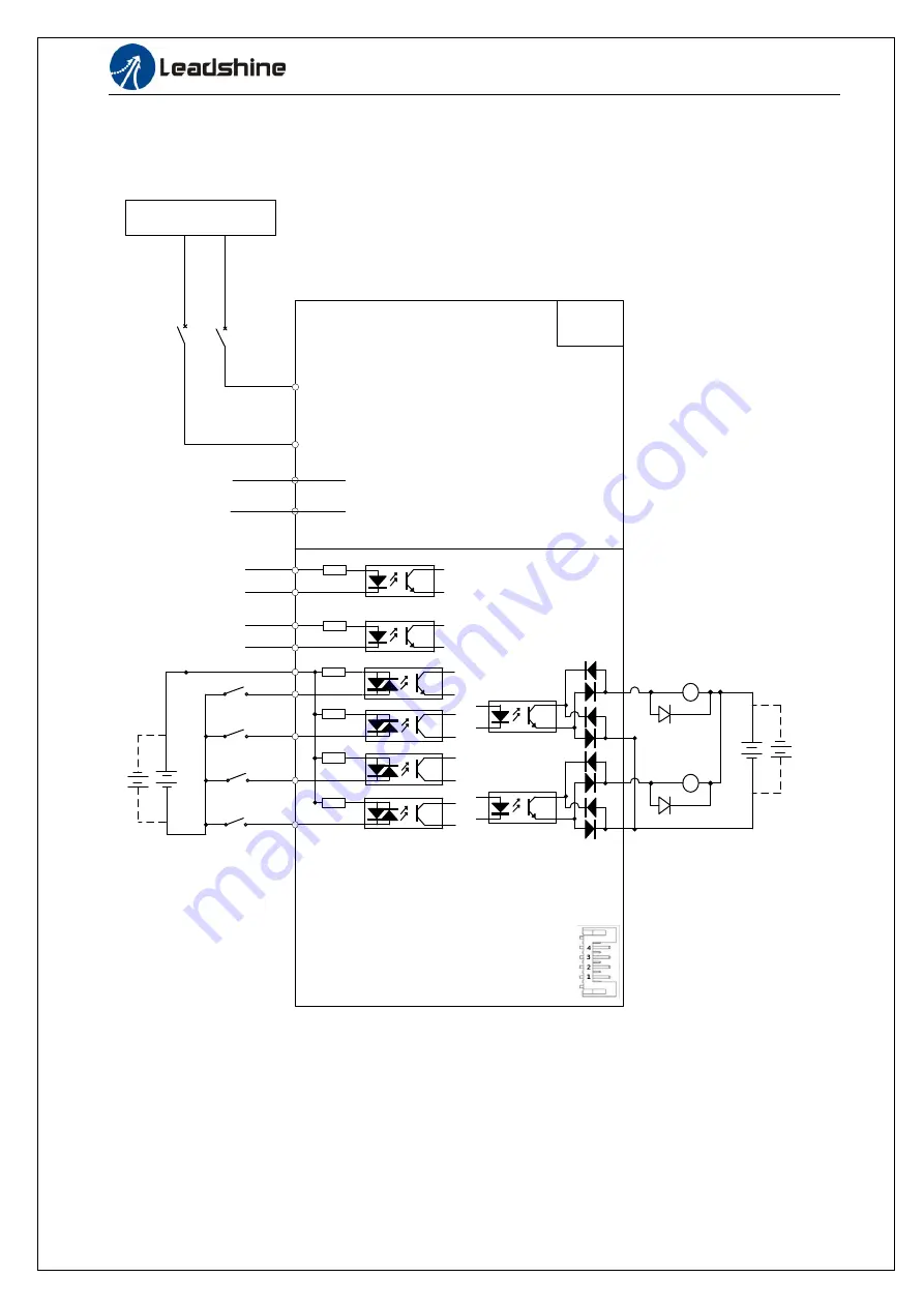
Figure 3.1 Position Control Mode Wiring
Notes:
1. 4 digital inputs DI3~DI6, support NPN and PNP connection, recommend 12~24V input signal.
2. 2 digital outputs DO1~DO2, support NPN and PNP connection, recommend 24V output signal.


