User Manual of iSV2-CAN Servo
www.leadshine.com
15
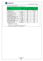
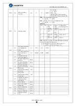
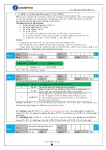
CAN Baud rate
SW1
SW2
Pr0.24
Default =1MHz
off
off
500
KHz
on
off
250
KHz
off
on
125
KHz
on
on
If SW1 and SW2 OFF, then Pr0.24 valid
If SW1 or SW2 ON, then these switch valid in higher priority than Pr0.24
SW3:
CAN terminal resistor
SW3=off
,
disconnect the terminal resistance
SW3=on
,
connect the terminal resistance
SW4
:
CAN Node-ID selection
(
High Bit
)
SW4=off, High Bit =0, CAN Node-ID=RCS
SW4=on, High Bit =1, CAN Node-ID =16+RCS
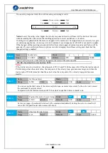
3.3 I/O Interface Principle
3.3.1 Digital Input Interface
4.7K
COMI
DI3
Figure 3-2
Digital Input Interface
(1)
The user provide power supply, DC 12-24V, current≥100mA
(2)
Notice:
if current polar connect reversely, servo motor doesn’t run.
3.3.2 Digital Output Interface
COMO
DO1
Single-ended output
Figure 3-3 Switch Output Interface
(1)
2 digital single-ended outputs DO1~DO2, support NPN and PNP connection, recommend 24V output
signal.
(2) If the load is inductive loads relays, etc., there must be anti-parallel freewheeling diode across the load. If
the freewheeling diode is connected reversely, the servo drive is damaged.
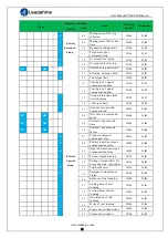
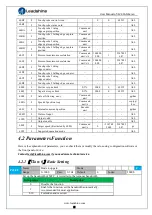
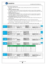
Digital Input function allocation
Pr4.02
Name
Input selection DI3
Mode
F
Range
0~00FFFFFFh
Unit
—
Default
0x14
Index
2402h
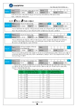
Pr4.03
Name
Input selection DI4
Mode
F
Range
0~00FFFFFFh
Unit
—
Default
0x16
Index
2403h


