background image


User Manual of iSV2-CAN Servo 


    www.leadshine.com


28 


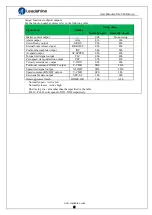
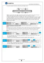
0:


Incremental  position mode

:   

The encoder is used as a incremental encoder, and the position retentive at power failure is not 
supported. 

1:


Absolute position linear mode

:   

The encoder is used as an absolute encoder, and the position retentive at power failure is supported.. 
It is applicable to the scenario where the travel range of device load is fixed and the encoder multi-turn 
data dose not overflow. 

2: Absolute position rotation mode

The encoder is used as an absolute encoder, and the position retentive at power failure is supported.. 
It is mainly applicable to the scenario  where the load travel range is not limited and the number of 
motor single-direction revolution is less  than 0~(Pr6.63+1) 

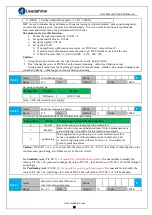
5: Clean multi-turn alarm

, and open multi-turn absolute function.   

It will become 1 when normal clearance, if it’s still 5 after 3seconds, please  deal with according to 153 
alarm processing. 

9: Clear multi-turn position and reset multi-turn alar

m, open multi-turn absolute function.   

It will become 1 when normal clearance, if it’s still 9 after 3seconds, please  deal with according to 153 

alarm processing.    Please remember to do mechanical  homing. 

Notes: 

Set to 9 after homing process  finished and servo disabled, valid after restart power-supply 


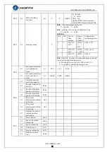
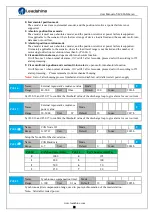
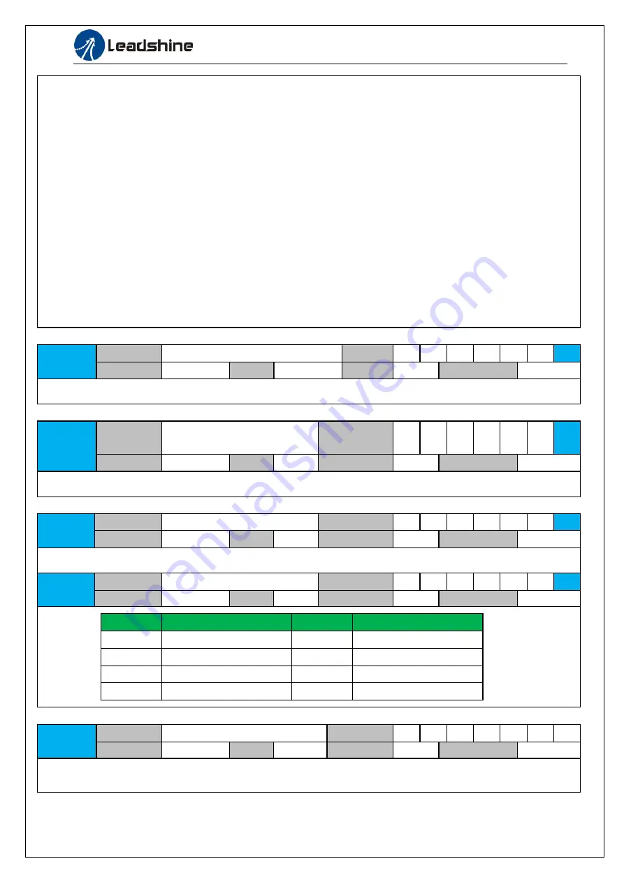
Pr0.16 

Name 

External regenerative resistance value 

Mode 


Range 

40~500 

Unit 

Ohm


Default 

100 

Index 

2016h 


Set Pr.0.16 and Pr.0.17 to confirm the threshold value of the discharge loop to give alarm for over current.  


Pr0.17 

Name 

External regenerative resistance 

power value 

Mode 


Range 

20~5000 

Unit 

Default 

20 

Index 

2017h 


Set Pr.0.16 and Pr.0.17 to confirm the threshold value of the discharge loop to give alarm for over current.  


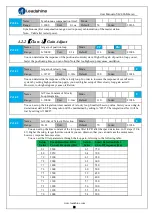
Pr0.23


Name 

CAN Node ID 

Mode 


Range 

0~32767 

Unit 

— 

Default 

Index 

2023h 


Setup the Node-ID of the slave station. 

Pr0.24


Name 

CAN Baud rate 

Mode 


Range 

0~7 

Unit 

— 

Default 

Index 

2024h 


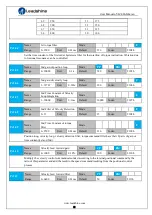
Pr0.24 

CAN baud rate (KHz) 

Pr0.24 

CAN baud rate (KHz) 

1000 

125 

800 

100 

500 

50 

250 

20 


Pr0.25 

Name 

Synchronous compensation time 1 

Mode 


Range 

1~100 

Unit 

0.1us 

Default 

10 

Index 

2025h 


Synchronous jitter compensation range, used in poor synchronization of the master station. 

Note

Valid after restart power. 
 

Summary of Contents for iSV2-CAN Series

Page 1: ...User Manual of iSV2 CAN Servo www leadshine com 1 User Manual Of iSV2 CAN Series Integrated Servo Motor Prelimilary version 0 01 ...

Page 2: ... result in loss of life or serious injury Caution indicates that the error operation could result in operator injured also make equipment damaged Attention indicates that the error use may damage product and equipment Safety precautions Warning The design and manufacture of product doesn t use in mechanic and system which have a threat to operator The safety protection must be provided in design a...

Page 3: ...gging should be run without loaded debugging with load can be done after confirming parameter setting correctly to prevent mechanical damage because of error operation Caution Install a emergency stop protection circuit externally the protection can stop running immediately to prevent accident happened and the power can be cut off immediately The run signal must be cut off before resetting alarm s...

Page 4: ... 5 CAN Node ID and Baud rate switch 14 3 3 I O Interface Principle 15 3 3 1 Digital Input Interface 15 3 3 2 Digital Output Interface 15 Chapter 4 Parameter 18 4 1 Parameter List 18 4 1 1 Drive Parameters Group 2000h 18 4 1 2 Manufacturer Parameters Group 5000h 21 4 1 3 Device Profile Parameters Group 6000h 23 4 2 Parameters Function 25 4 2 1 Class 0 Basic Setting 25 4 2 2 Class 1 Gain Adjust 29 4...

Page 5: ...ntrolword in profile position mode 66 6 5 2 Statusword in profile position mode 67 6 5 3 Related objects 67 6 5 4 Example of profile position mode 68 6 6 Profile velocity mode 68 6 6 1 Controlword in profile velocity mode 69 6 6 2 Statusword in profile velocity mode 69 6 6 3 Related objects 69 6 6 4 Example of profile velocity mode 70 6 7 Profile torque mode 70 6 7 1 Controlword in profile torque ...

Page 6: ...on 91 6 10 2 Motion Studio inertia ratio identification 91 6 11 Vibration Suppression 92 6 12 Friction torque compensation 94 6 13 Regenerative resister setting 94 Chapter 7 Alarm and Processing 96 7 1 Alarm List 96 7 2 Alarm Processing Method 97 Chapter 8 Product Specification 105 8 1 Drive Technical Specification 105 8 2 Accessory selection 106 Contact us 107 ...

Page 7: ...Protocol CAN Field bus Application Layer Protocol CANopen Protocol CAN ID type CAN 2 0A Communication Rate 1M 500k 250k 100k 50k 20k bit s Sub protocol DS301 V4 02 DSP 402 V2 0 PDO Transmission Modes Time trigger event trigger asynchronization synchronization Control mode profile position profile velocity profile torque homing 1 1 1 Specification and feature Part Number iSV2 CAN6020V48 iSV2 CAN604...

Page 8: ...al Communication CANopen RS 232 for tuning 1 1 2 Part Numbering Information iSV2 CAN 6040 V48 B Motor with brake Voltage 24 24V 48 48V Maximum Output Power 6020 60mm frame size 200W 6040 60mm frame size 400W 8075 80mm frame size 750W RS RS485 Pulse Dir RS485 CAN CANopen iSV2 servo motor 24 70Vdc 1 2 Inspectionof product Check thefollowing thing beforeusing the products a Check if the product is da...

Page 9: ... than 1000m Vibration Less than 0 5G 4 9m s2 10 60Hz non continuous working Protection level IP20 no protection 2 2 Servo Drive Installation Notice Must install in control cabinet with sufficient safeguarding grade Must install with specified direction and intervals and ensure good cooling condition Don t install them on inflammable substance or near it to prevent fire hazard Notice Don t hold the...

Page 10: ...ter the diameter 0 14mm2 AWG24 26 the shield should be connected to FG terminal Length of line cable length should be as short as possible and control CN1 cable is no more than 3 meters the CN2 cable length of the feedback signal is no more than 10 meters Wiring be away from the wiring of power line to prevent interference input Install a surge absorbing element for the relevant inductive element ...

Page 11: ...ce of the same specification or even more power in this case cancel the built in resistance If d14 is too large or accumulates too fast it means that the regenerative energy is too large and the built in resistance cannot consume the generated energy the regenerative energy power will be reduced or the external resistance with higher resistance value or power will be reduced If an overvoltage erro...

Page 12: ...r Supply 270Ω 4 7K 4 7K 4 7K 4 7K 9 8 COM_OUT 24Vdc output 10 11 12 DO1 DO2 BR BR Regenerative resistor NC POT NOT CAN 2 Figure 3 1 Position Control Mode Wiring Notes 1 4 digital inputs DI3 DI6 support NPN and PNP connection recommend 12 24V input signal 2 2 digital outputs DO1 DO2 support NPN and PNP connection recommend 24V output signal ...

Page 13: ... 3 default value is E STOP signal low level available in default max voltage is 24V input 20KHz 7 DI4 Input Digital input signal 4 default value is homing switch signal HOME SWITCH low level available in default max voltage is 24V input 20KHz 8 DI5 Input Digital input signal 5 default value is Positive limit switch signal POT low level available in default max voltage is 24V input 20KHz 9 DI6 Inpu...

Page 14: ...resistor The recommend resistor for most application is 10Ω 5 100watt Leadshine can provide resistor RXFB 1 Part num Code 10100469 3 2 3 Communication Port CN3 Pin Signal RS232 1 5V 2 TX 3 GND 4 RX 3 2 4 CAN bus connector CN4 Pin Signal CAN 1 CANH 2 CANL 3 GND 4 PE 3 2 5 CAN Node ID and Baud rate switch RCS NO CAN Node ID NO CAN Node ID 0 Pr0 23 Default 16 8 8 1 1 9 9 2 2 A 10 3 3 B 11 4 4 C 12 5 ...

Page 15: ...igure 3 2 Digital Input Interface 1 The user provide power supply DC 12 24V current 100mA 2 Notice if current polar connect reversely servo motor doesn t run 3 3 2 Digital Output Interface COMO DO1 Single ended output Figure 3 3 Switch Output Interface 1 2 digital single ended outputs DO1 DO2 support NPN and PNP connection recommend 24V output signal 2 If the load is inductive loads relays etc the...

Page 16: ... 14h 94h HOME SWITCH HOME SWITCH 16h 96h 2 Normally open means input signal comes from external controller or component for example PLC Normally closed means input signal comes from drive internally Don t setup to a value other than that specified in the table Don t assign specific function to 2 or more signals Duplicated assignment will cause Err210 I F input multiple assignment error 1or Err211 ...

Page 17: ... complete output INP 04h 84h At speed output AT SPPED 05h 85h Torque limit signal output TLC 06h 86h Zero speed clamp detection output ZSP 07h 87h Velocity coincidence output V COIN 08h 88h Positional command ON OFF output P CMD 0Bh 8Bh Speed limit signal output V LIMIT 0Dh 8Dh Speed command ON OFF output V CMD 0Fh 8Fh Servo enable state output SRV ST 12h 92h Homing process finish HOME OK 22h A2h ...

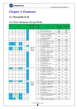
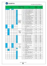
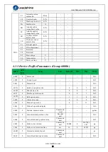
Page 18: ... Pr_016 F 17 External regenerative resistance power value 2017h Pr_017 F 23 CAN Node ID 2023h Pr_023 F 24 CAN baud rate 2024h Pr_024 25 Synchronous compensation time 1 2025h Pr_025 26 Synchronous compensation time 2 2026h Pr_026 PP HM Class 1 Gain Adjust 00 1st gain of position loop 2100h Pr_100 F 01 1st gain of velocity loop 2101h Pr_101 F 02 1st time constant of velocity loop integration 2102h P...

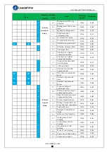
Page 19: ...3 PV Class 3 Speed Torque Control 12 time setup acceleration 2312h Pr_312 PV 13 time setup deceleration 2313h Pr_313 PV 14 Sigmoid acceleration deceleration time setup 2314h Pr_314 PV 16 Speed zero clamp level 2316h Pr_316 23 Speed mode zero speed static 2323h Pr_323 F Class 4 I F Monitor Setting 00 input selection DI1 2400h Pr_400 F 01 input selection DI2 2401h Pr_401 F 02 input selection DI3 240...

Page 20: ...que limit 2539h Pr_539 Class 6 Special Setup 01 Encoder zero position compensation 2601h Pr_601 PP HM 04 JOG trial run command speed 2604h Pr_604 PP HM 05 Position 3rd gain valid time 2605h Pr_605 PP HM 06 Position 3rd gain scale factor 2606h Pr_606 F 07 Torque command additionalvalue 2607h Pr_607 F 08 Positive direction torque compensation value 2608h Pr_608 F 09 Negative direction torque compens...

Page 21: ... 0 65535 83Bh Alarm detection 06 Reserved 0 65535 07 Sync0 Watchdog limit 4 0 65535 08 Sync0 Drift watchdogcounter 0 0 65535 83Ch Alarm detection 09 Sync0 Drift watchdoglimit 4 0 65535 0A SM2 watchdog counter 0 0 65535 83Ah Alarm detection 0B SM2 Watchdog limit 4 0 65535 0C Application layer SM2 Sync0 watchdogcounter 0 0D Application layer SM2 Sync0 watchdoglimit 4 0E Reserved 0 500 0F Time interv...

Page 22: ...avel between the high speed and low speed during homing process 0 Homing process error set 6041h bit13 1 1 As normal continue homing process 5400 01 Set synchronization cycle minimum value us 250 125 1000 02 Set synchronization cycle maximum value us 10000 4000 20000 5500 01 Absolute encoder multi turn number r 02 Encoder single turn position Pulse 03 Encoder feedback position 32 bit low Pulse 04 ...

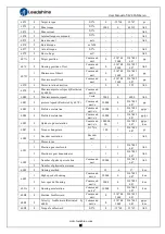
Page 23: ...t Min Max Mode 603F 0 Error code ALL 6040 0 Control word ALL 6041 0 Statusword ALL 605A 0 Quick stop option code 6 0 7 ALL 605B 0 Shut down code 0 0 1 ALL 605C 0 Disable operation code 0 0 1 ALL 605D 0 Halt option code 1 1 4 ALL 605E 0 Alarm stop code 0 0 2 ALL 6060 0 Mode of operation 8 1 11 ALL 6061 0 Mode of operation display ALL 6062 0 Position demand value Command unit pp hm 6063 0 Actual int...

Page 24: ... 0 2147483 647 pp 6083 0 Profile acceleration Command unit s s 10000 1 2147483 647 pp pv 6084 0 Profile deceleration Command unit s s 10000 1 2147483 647 pp pv 6085 0 Quick stop deceleration Command unit s s 100000 00 1 2147483 647 pp pv hm 6087 0 Torque change rate 0 1 s 100 1 2147483 647 pt 608F 1 Encoder resolution Encoder unit ALL 2 Motor turns 6091 1 Electron gear molecule 1 1 2147483 647 ALL...

Page 25: ...imit 0 1 3000 0 65535 ALL 60E1 0 Negative torque limit 0 1 3000 0 65535 ALL 60F4 0 Actual following error Command unit pp hm 60FA 0 Speed of position loop Command unit s csp pp hm 60FC 0 Internalcommand position Encoder unit pp hm 60FD 0 Statusof input ALL 60FE 1 Output valid ALL 2 Output enable ALL 60FF 0 Target speed Restricted by 6080 Command unit s 0 214748 3648 2147483 647 pv 6502 0 Supported...

Page 26: ...ils 8 CANopen PP PV PT HM Note valid after restart power supply Pr0 02 Name Real time Auto gain Tuning Mode F Range 0 2 Unit Default 0 Index 2002h You can set up the action mode of the real time auto gain tuning Setup value Mode Varying degree of load inertia in motion 0 invalid Real time auto gain tuning function is disabled 1 standard Basic mode do not use unbalanced load friction compensation o...

Page 27: ...lt 250 Index 2004h You can set up the ratio of the load inertia against the rotor of the motor inertia Pr0 04 load inertia rotate inertia 100 Notice If the inertia ratio is correctly set the setup unit of Pr1 01 and Pr1 06 becomes Hz When the inertia ratio of Pr0 04 is larger than the actual value the setup unit of the velocity loop gain becomes larger and when the inertia ratio of Pr0 04 is small...

Page 28: ...absolute function It will become 1 when normal clearance if it s still 9 after 3seconds please deal with according to 153 alarm processing Please remember to do mechanical homing Notes Set to 9 after homing process finished and servo disabled valid after restart power supply Pr0 16 Name External regenerative resistance value Mode F Range 40 500 Unit Ohm Default 100 Index 2016h Set Pr 0 16 and Pr 0...

Page 29: ...igh setup may cause oscillation Pr1 02 Name 1st Time Constant of Velocity Loop Integration Mode F Range 1 10000 Unit 0 1ms Default 310 Index 2102h You can set up the integration time constant of velocity loop Smaller the setup value faster you can dog in deviation at stall to 0 The integration will be maintained by setting to 9999 The integration effect will be lost by setting to 10000 Pr1 03 Name...

Page 30: ...ion Mode F Range 1 10000 Unit 0 1ms Default 10000 Index 2107h Pr1 08 Name 2nd Filter of Velocity Detection Mode F Range 0 31 Unit Default 15 Index 2108h Pr1 09 Name 2nd Time Constant of torque filter Mode F Range 0 2500 Unit 0 01ms Default 126 Index 2109h Position loop velocity loop velocity detection filter torque command filter have their 2 pairs of gain or time constant 1st and 2nd Pr1 10 Name ...

Page 31: ...ange while driving in trapezoidal speed pattern under ideal condition where disturbance torque is not active Pr1 13 Name Torque feed forward filter Mode PP PV HM Range 0 6400 Unit 0 01ms Default 0 Index 2113h Set up the time constant of 1st delay filter which affects the input of torque feed forward zero positional deviation is impossible in actual situation because of disturbance torque as with t...

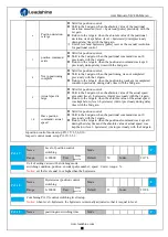
Page 32: ...in when the absolute value of the actual speed exceeded level hysteresis r min previously with the 1st gain Return to the 1st gain when the absolute value of the actual speed was kept below level hysteresis r min previously during delay time with the 2nd gain 10 Have position command actual speed Valid for position control Shift to the 2nd gain when the positional command was not 0 previously with...

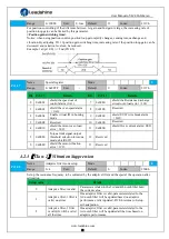
Page 33: ...ng mode 9 0x0200 shield UVW wire break alarm 0A3 3 0x0008 Reserved 10 0x0400 Reserved 4 0x0010 shield the motor over load error 100 11 0x0800 shield Over current alarm 0E0 5 0x0020 Torque limit signal output threshold selection in torque mode shield 6071 12 Reserved 6 0x0040 shield the motor vibration error 190 13 Reserved 4 2 3 Class 2 Vibration Suppression Pr2 00 Name Adaptive filter mode setup ...

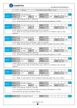
Page 34: ...e 2nd notch frequency Mode F Range 50 2000 Unit Hz Default 2000 Index 2204h Set the center frequency of the 2nd notch filter Notice the notch filter function will be invalidated by setting up this parameter to 2000 Pr2 05 Name 2nd notch width selection Mode F Range 0 20 Unit Default 2 Index 2205h Set the width of notch at the center frequency of the 2nd notch filter Notice Higher the setup larger ...

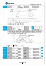
Page 35: ...lay filter in response to the positional command When a square wave command for the target speed Vc is applied set up the time constant of the 1st delay filter as shown in the figure below Pr2 23 Name positional command FIR filter Mode PP HM Range 0 10000 Unit 0 1ms Default 0 Index 2223h Set up the time constant of the1st delay filter in response to the positional command When a square wave comman...

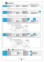
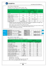
Page 36: ...000 Pr3 12 1ms Deceleration time ms Vc 1000 Pr3 13 1ms Pr3 14 Name Sigmoid acceleration deceleration time setup Mode PV Range 0 1000 Unit ms Default 0 Index 2314h Set S curve time for acceleration deceleration process when the speed command is applied According to Pr3 12Acceleration time setup and Pr3 13 Deceleration time setup set up sigmoid time with time width centering the inflection point of ...

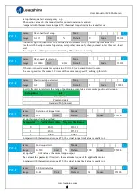
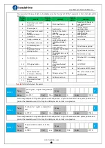
Page 37: ...STOP Associated parameter Pr4 43 Pr4 10 Name Output selection DO1 Mode F Range 0 00FFFFFFh Unit Default 0x81 Index 2410h Pr4 11 Name Output selection DO2 Mode F Range 0 00FFFFFFh Unit Default 0x02 Index 2411h Assign functions to digital outputs This parameter use 16 binary system do setup For the function number please refer to the following table Signal name Symbol Setup Value Normally open Norma...

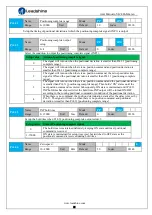
Page 38: ...no position command and the positional deviation is smaller than Pr4 31 positioning complete range Then holds ON states until the next position command is entered Subsequently ON state is maintained until Pr4 33 INP hold time has elapsed After the hold time INP output will be turned ON OFF according to the coming positional command or condition of the positional deviation 4 When there is no comman...

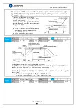
Page 39: ...h positive and negative direction regardless of the motor rotating direction There is hysteresis of 10 r min Pr4 35 Name Speed coincidence range Mode PV Range 10 2000 Unit RPM Default 50 Index 2435h Set the speed coincidence V COIN output detection timing Output the speed coincidence V COIN when the difference between the speed command and the motor speed is equal to or smaller than the speed spec...

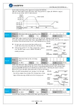
Page 40: ...ter setting up Pr4 37 tb then compose the sequence so as the drive turns to servo off after the brake is actually activated Pr4 38 Name Mechanical brake action at running setup Mode F Range 0 10000 Unit 1ms Default 0 Index 2438h Mechanical brake start delay time setup mainly used to prevent servo off galloping phenomenon Set up time from when detecting the off of servo on input signal SRV ON is to...

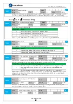
Page 41: ...e free run to stop Pr5 08 Name LV trip selection at main power OFF Mode F Range 0 1 Unit Default 1 Index 2508h You can select whether or not to activate Err0d 0 main power under voltage protection function while the main shutoff continues for the setup of Pr5 09 The main power OFF detection time Setup value Action of main power low voltage protection 0 When the main power is shut off during Servo ...

Page 42: ...comes 1 2 times of the motor max speed by setting up this to 0 Pr5 20 Name Position setup unit select Mode F Range 0 2 Unit Default 2 Index 2520h Specify the unit to determine the range of positioning complete and excessive positional deviation Setup value unit 0 Encoder unit 1 Command unit 2 Standard 2500 line unit Pr5 21 Name Selection of torque limit Mode F Range 0 2 Unit Default 0 Index 2521h ...

Page 43: ...ype 9 Control mode 24 Encoder positional deviation encoder unit 39 Whether DC is running or not 10 I O signal status 25 Motor electromechanical angle 40 ACC DEC 11 26 Motor mechanical Angle 41 Sub index of OD index 12 Error factor and reference of history 27 Voltage across PN 42 The value of sub index of OD index 13 Alarm code 28 Software version 14 Regenerative load factor 29 Notes Valid after re...

Page 44: ...x 2601h The Angle of the encoder after zero correction Pr6 04 Name JOG trial run command speed Mode F Range 0 10000 Unit r min Default 300 Index 2604h You can set up the command speed used for JOG trial run velocity control Pr6 05 Name Position 3rd gain valid time Mode PP HM Range 0 10000 Unit 0 1ms Default 0 Index 2605h Set up the time at which 3rd gain becomes valid When not using this parameter...

Page 45: ...f the motor ratio PR6 13 load inertia rotor inertia 100 Pr6 14 Name Emergency stop time at alarm Mode F Range 0 3000 Unit ms Default 200 Index 2614h Set up the time allowed to complete emergency stop in an alarm condition exceeding this time puts this system in alarm state Pr6 20 Name Trial run distance Mode F Range 0 1200 Unit 0 1rev Default 10 Index 2620h The distance of running each time in JOG...

Page 46: ... Z signal for homing process Pr6 62 Name Overload warning threshold Mode F Range 0 99 Unit Default 0 Index 2662h Before an overload alarm pre alarm Pr6 63 Name upper limit of multi turn absolute position Mode F Range 0 32766 Unit r Default 0 Index 2663h While Pr0 15 2 the feedback position will loop between 0 Pr6 63 1 Encoder resolution 4 2 8 Class 7 Factory setting Pr7 31 Name Regenerative resist...

Page 47: ...nition Halt Fault reset Mode specific Enable operation Quick stop Enable voltage Switch on Index 6041H Name Status word Structure VAR Type Uint 16 Access RO Mapping TPDO Mode ALL Range 0 0XF FFF Default 0 Bit 7 6 5 4 3 2 1 0 Definition Reserved Switch on disabled Quick stop Voltage output Fault Operation enable Switch on Ready to switch on Bit 15 14 13 12 11 10 9 8 Definition Reserved Reserved Mod...

Page 48: ... RW Mapping Mode ALL Range 1 3 Default 1 PP PV Mode 1 Stop according to 6084h Profile deceleration keeping Operation enabled 2 Stop according to 6085h Quick stop deceleration keeping Operation enabled 3 Stop according to 6072h Max torque 60C6h Max deceleration Stop according to torque 0Operation enabled HM Mode 1 Stop according to 609Ah Homing acceleration keeping Operation enabled 2 Stop accordin...

Page 49: ...he opposite direction as the position command HM Velocity mode PV 0 Rotate in the same direction as the position command 64 Rotate in the opposite direction as the position command ALL mode 0 Rotate in the same direction as the position command 224 Rotate in the opposite direction as the position command Index 608FH 0 1 Name Encoder resolution Structure VAR Type Dint 32 Access R0 Mapping TPDO Mode...

Page 50: ...arch the homing point in positive direction deceleration point is homing switch homing point is motor Z signal the falling edge on the same side of homing switch must come before Z signal 4 Search the homing point in negative direction deceleration point is homing switch homing point is motor Z signal the rising edge on the same side of homing switch must come before Z signal 5 Search the homing p...

Page 51: ...ode ALL Range 0 ffff Default The bits of a 60FDh object are functionally defined as follow Bit31 Bit30 Bit29 Bit28 Bit27 Bit26 Bit25 Bit24 Z signal Reserved Reserved Reserved Touch Probe 2 Touch Probe 1 BRAKE INP V COIN TLC Bit23 Bit22 Bit21 Bit20 Bit19 Bit18 Bit17 Bit16 E STOP Reserved Reserved Reserved Reserved Reserved SI14 SI13 Bit15 Bit14 Bit13 Bit12 Bit11 Bit10 Bit9 Bit8 SI12 SI11 SI10 SI9 S...

Page 52: ...ices off road and rail vehicles maritime electronics building automation power generation etc The CANopen protocol defines basically two aspects of the communication protocol how the communication should be formatted CANopen frame and what objects are defined in common Those objects may be used to configure or arbitrate the communication or simply to exchange application data Communication objects...

Page 53: ...ictionary Emergency 0001b 0x080 Node ID 1024H 1015H TXPDO1 transmit 0011b 0x180 Node ID 1800H RXPDO1 receive 0100b 0x200 Node ID 1400H TXPDO2 transmit 0101b 0x280 Node ID 1801H RXPDO2 receive 0110b 0x300 Node ID 1401H TXPDO3 transmit 0111b 0x380 Node ID 1802H RXPDO3 receive 1000b 0x400 Node ID 1402H TXPDO4 transmit 1001b 0x480 Node ID 1803H RXPDO4 receive 1010b 0x500 Node ID 1403H SDO transmit 101...

Page 54: ...chine defines the communication status for CANopen devices NMT state machine Transition Event 1 After power on the system goes directly to initialization state 1 Once initialization is completed the system enters to Pre operational state 3 6 Reception of Start remote node command 4 7 Reception of Enter pre operational state command 5 8 Reception of Stop remote node command 9 10 11 Reception of Res...

Page 55: ... be executed if the devices involved in the communication are in the appropriate communication states 5 3 1 NMT services The structure of each NMT service command is as follows COB ID hex Number of Bytes Data field Byte 0 Byte 1 0x000 2 Command specifier Node ID The possible NMT services commands are the followings Command specifier hex Command description 01 Start remote node 02 Stop remote node ...

Page 56: ... Bytes Data hex Description 701 0 Master sends a CAN remote frame without data to node 1 701 1 7F Node 1 sends the actual NMT state pre operational toggling the 7th bit 701 0 0 Master sends a CAN remote frame without data to node 1 701 1 FF Node 1 sends the actual NMT state pre operational toggling the 7th bit Protocol heartbeat The heartbeat protocol defines an error control service without need ...

Page 57: ...er sends a CAN remote frame without data to node 1 Delay Higher than Guard Time Life Time Factor 81 8 0 30 81 11 00 00 00 00 00 Node 1 send an EMCY indicating the lifeguard error Protocol boot up An NMT slave issues the Boot up message to indicate to the NMT Master that it has entered the state Pre operational from state Inititalising Example of NMT Boot up COB ID hex Number of Bytes Data hex Desc...

Page 58: ...le CAN frame and can contain multiple object dictionary entries with a maximum of 8 bytes of data Each PDO has an identifier and is transmitted by only one node in the network however it could be received by more than one node PDOs must be configured previous to using them There are two types of PDO messages Transmit PDO TPDO and Receive PDO RPDO The trigger event of the PDO message could be confi...

Page 59: ...ption 202 2 22 12 Master sends a RPDO1 to Node 2 with a content value of 0x1222 5 6 SYNC SYNC object is a broadcast message sent by one of the devices in the bus normally the master to provide synchronization to the network and to allow coordination between nodes The nodes could be programmed to return any variable actual position etc by means of TPDO at reception of SYNC object The SYNC object ha...

Page 60: ...8141H CAN Bus off occurred 8150H Send COB ID conflicts 8210H PDO not processed due to length error 8220H PDO exceeds length error iSV2 CAN series include Error registers Object 0x1001 Bit Description 0 Generic Error 1 Current 2 Voltage 3 Temperature 4 Communication 5 Error specified by device protocol 6 Reserved 7 Leadshine specific error ...

Page 61: ...g power input lines and motor output lines are forbidden and no short connected with PG ground 2 Confirmation of power supply The range of control power input Vdc GND must be in the rated range 24 60Vdc 3 Fixing of position the motor and drive must be firmly fixed 4 Inspection without load the motor shaft must not be with a mechanical load 5 Inspection on control signal 1 all of the control switch...

Page 62: ...is allowed Ready The servo drive is ready Parameter setting of the servo drive is allowed Wait to switch on The servo drive waits to switch on Parameter setting of the servo drive is allowed Running The servo drive is in normal running state a certain control mode is enabled The motor is energized and rotates when the reference is not 0 Parameters with the setting condition of during running can b...

Page 63: ...protocol position mode PP and homing mode HM only in these two modes does the electronic gear ratio valid Electronic gear ratio range is 1 1000 8000 otherwise ErA00 warning will appear the warning is not saved after modification to a reasonable range the operation panel alarm will automatically disappear but the 402 state will still be in the error state write 0x80 into 6040h to reset The electron...

Page 64: ...000h 7 9 10 12 Quick stop 0 0 1 0002h 7 10 11 Operation disable 0 0 1 1 1 0007h 5 Operation enable 0 1 1 1 1 000Fh 4 16 Fault reset Rising edge 0080h 15 is not affected by this bit state indicates that this transition is performed in the device start state indicates that it has no effect on the start state and remains in the start state 1 The state machine switch corresponds to figure 6 1 The defi...

Page 65: ...0000 Not ready to switch on 1 0000 Switch on disabled 01 0001 Ready to switch on 01 0011 Switch on 01 0111 Operation enabled 00 0111 Quick stop active 0 1111 Fault reaction active 0 1000 Fault is not affected by this bit state The definition of bit 8 and bit 12 13 in different operation modes are shown in the following table Bit Operation Mode Profile Position PP Profile Velocity PV Profile Torque...

Page 66: ...ion starts Nevertheless if there was a previous set point being processed the behavior of the system depends on the Change set immediately bit in the controlword If the Change set immediately bit of the controlword is 1 the target point is the new set point and motion is started to reach this new set point If the Change set immediately bit of the controlword is 0 the new set point is added to a bu...

Page 67: ...in profile position mode The binary representation of the statusword 6041 in profile position mode is as follows Bit Definition 15 14 Reserved 13 Following error 12 11 Position limit active 10 Target reached 9 Remote 8 Abnormal stop 7 Reserved 6 Switch on disabled 5 Quick stop 4 Voltage output 3 Fault 2 Operation enable 1 Switch on 0 Ready to switch on The meaning of each bit is described below de...

Page 68: ...rvo Enabled 6 2f 60 60 00 01 00 00 00 Write operation mode as 1H profile position mode 7 23 81 60 00 90 D0 03 00 Write the protocol speed as 3D090H 1500rpm 10000p r 8 23 83 60 00 90 D0 03 00 Write the protocol acceleration as 3D090H 1500rpm s 10000p r 9 23 7a 60 00 20 4E 00 00 Write the target location at 4E20H 2 rotations 10000p r 10 2b 40 60 00 4f 00 00 00 Write the control word as 4fH Set to re...

Page 69: ...t 1 Stop the movement 6 6 2 Statusword in profile velocity mode The binary representation of the statusword 6041 in profile velocity mode is as follows Bit Definition 15 14 13 12 Velocity is 0 11 10 Target reached 9 8 7 6 Switch on disabled 5 Quick stop 4 Voltage output 3 Fault 2 Operation enable 1 Switch on 0 Ready to switch on The meaning of each bit is described below depending on its value Nam...

Page 70: ...d as 0fH state machine switching status Switched On Operation Enable Servo Enabled 6 2f 60 60 00 03 00 00 00 Write operation mode as 3H profile velocity mode 7 23 83 60 00 90D0 03 00 Write the protocol acceleration as 3D090H 1500rpm s 10000p r 8 23 ff 60 00 90 D0 03 00 Write the protocol speed as 3D090H 1500rpm 10000p r 9 2b 40 60 00 07 00 00 00 Write control word as 07H state machine switching st...

Page 71: ...epresentation of the statusword 6041 in profile torque mode is as follows Bit Definition 15 14 13 12 11 10 Target reached 9 8 7 6 Switch on disabled 5 Quick stop 4 Voltage output 3 Fault 2 Operation enable 1 Switch on 0 Ready to switch on The meaning of each bit is described below depending on its value Name Value Description Target reached 0 Halt 0 Target torque not reached Halt 1 Axis decelerate...

Page 72: ...00 Write operation mode as 4H profile torque mode 7 23 71 60 00 14 00 00 00 Write the torque value as 14H 20 0 1 1 rated torque 8 2b 74 20 00 e8 03 00 00 Write the speed limit Pr3 21 as 3e8H 1000 RPM 9 23 87 60 00 14 00 00 00 Write the rate of change in torque as 14H That is increases to 20 0 1 of the rated torque 2 s 10 2b 40 60 00 07 00 00 00 Write control word as 07H state machine switching sta...

Page 73: ...presentation of the statusword 6041 in profile homing mode is as follows Bit Definition 15 14 13 Homing error 12 Homing attained 11 10 Target reached 9 8 Abnormal stop 7 6 Switch on disabled 5 Quick stop 4 Voltage output 3 Fault 2 Operation enable 1 Switch on 0 Ready to switch on The meaning of each bit is described below depending on its value Homing error Homing attained Target reached Descripti...

Page 74: ...t is hexadecimal 3 2b 40 60 00 06 00 00 00 Write control word as 06H state machine switching status Switch On Disabled Ready to Switch On 4 2b 40 60 00 07 00 00 00 Read control word as 07H state machine switching status Ready to Switch On Switched On The relay in the actuator is engaged at this point 5 2b 40 60 00 0f 00 00 00 Write control word as 0fH state machine switching status Switched On Ope...

Page 75: ... 5 Search the homing point with low speed positive direction when the torque reached then stop immediately Start Position Stop Position Low speed of homing 6099h 02h Method 4 Search the homing point with low speed negative direction when the torque reached then change the motion direction when the torque is gone then stop immediately Start position Stop Position High speed 6099h 01h Low speed 6099...

Page 76: ...tor stops after leaving the negative limit switch and the first encoder Z signal is valid as shown in figure If the positive limit signal is valid during the homing process the status word 6041h bit 13 will be valid indicating that the homing error and the motor will stop immediately Z signal NOT signal A B Start Position Stop Position High speed 6099h 01h Low speed 6099h 02h Method 2 If the posit...

Page 77: ... signal is valid during the homing process the status word 6041h bit 13 will be valid indicating that the homing error and the motor will stop immediately Z signal HOME SWITCH A B Start Position Stop Position High speed 6099h 01h Low speed 6099h 02h Method 4 If the homing switch is invalid the motor will move in positive direction at low speed until the homing switch signal is valid The motor stop...

Page 78: ...the status word 6041h bit 13 will be valid indicating that the homing error and the motor will stop immediately Z signal HOME SWITCH A B Start Position Stop Position High speed 6099h 01h Low speed 6099h 02h Method 6 If the homing switch is invalid the motor will move in negative direction at low speed until the homing switch signal is valid The motor stops after leaving the homing switch and the f...

Page 79: ...igh speed until the positive limit switch valid Then the motor reverse the direction at low speed The motor stops after the homing switch valid and the first encoder Z signal is valid as shown in figure If the negative limit switch signal is valid during the homing process the status word 6041h bit 13 will be valid indicating that the homing error and the motor will stop immediately Z signal HOME ...

Page 80: ...high speed until the homing switch invalid Then the motor reverse the direction at low speed The motor stops after the homing switch valid and the first encoder Z signal is valid as shown in figure If the positive limit switch is invalid and motor stops at the homing switch position when it starts to move the motor will move in positive direction at high speed until the homing switch signal is inv...

Page 81: ...ter the homing switch invalid and the first encoder Z signal is valid as shown in figure If the homing switch and positive limit switch is invalid the motor will move in positive direction at low speed until the positive limit switch valid Then the motor reverse the direction at high speed until the homing switch valid Then the motor move in positive direction at low speed The motor stops after th...

Page 82: ...he motor will stop immediately Z signal HOME SWITCH B Start Position Stop Position High speed 6099h 01h Low speed 6099h 02h NOT signal A C Method 12 If the homing switch and positive limit switch is invalid the motor will move in negative direction at low speed The motor stops after the homing switch valid and the first encoder Z signal is valid as shown in figure If the negative limit switch is i...

Page 83: ...ection at high speed until the homing switch signal is invalid Then the motor reverse the direction at low speed The motor stops after the homing switch valid and the first encoder Z signal is valid as shown in figure If the homing switch and positive limit switch is invalid the motor will move in negative direction at high speed until the negative limit switch valid Then the motor reverse the dir...

Page 84: ...alid the motor will move in negative direction at low speed until the negative limit switch valid Then the motor reverse the direction at high speed until the homing switch valid Then the motor move in negative direction at low speed The motor stops after the homing switch invalid and the first encoder Z signal is valid as shown in figure If the positive limit switch signal is valid during the hom...

Page 85: ... SWITCH A B Start Position Stop Position High speed 6099h 01h Low speed 6099h 02h Method 20 This method is similar to method 4 HOME SWITCH A B Start Position Stop Position High speed 6099h 01h Low speed 6099h 02h Method 21 This method is similar to method 5 HOME SWITCH A B Start Position Stop Postion High speed 6099h 01h Low speed 6099h 02h Method 22 This method is similar to method 6 ...

Page 86: ...02h Method 23 This method is similar to method 7 HOME SWITCH B Start Position Stop Potion High speed 6099h 01h Low speed 6099h 02h POT signal A C Method 24 This method is similar to method 8 HOME SWITCH B Start Position Stop Position High speed 6099h 01h Low speed 6099h 02h POT signal A C Method 25 This method is similar to method 9 ...

Page 87: ...speed 6099h 02h POT signal A C Method 26 This method is similar to method 10 HOME SWITCH B Start Position Stop Position High speed 6099h 01h Low speed 6099h 02h POT signal A C Method 27 This method is similar to method 11 HOME SWITCH B Start Position Stop Position High speed 6099h 01h Low speed 6099h 02h NOT signal A C ...

Page 88: ...gh speed 6099h 01h Low speed 6099h 02h NOT signal A C Method 29 This method is similar to method 13 HOME SWITCH B Start Position Stop Position High speed 6099h 01h Low speed 6099h 02h NOT signal A C Method 30 This method is similar to method 14 HOME SWITCH B Start Position Stop Position High speed 6099h 01h Low speed 6099h 02h NOT signal A C ...

Page 89: ...n as homing point When using this method the motor does not need to be enabled only the control word 6041h needs to be executed from 0 to 1 Start Position Stop Position High speed 6099h 01h Low speed 6099h 02h Current position Control word 6040h bit4 0 1 6 9 SecurityFeatures 6 9 1 BRK OFF output This function can be configured by set digital DO output functions allocation refer to IO Pr4 10 parame...

Page 90: ... running At servo OFF during the motor is running tb of the right fig will be a shorter one of either Pr4 38 setup time or time lapse till the motor speed falls below Pr4 39 setup speed Pr4 39 Name Brake release speed setup Mode F Range 30 3000 Unit 1ms Default 30 Index 2439h Set up the speed timing of brake output checking during operation SRV_ON BRK_OFF Motor power on Brake action Velocity Brake...

Page 91: ...value the setup unit of the velocity loop gain becomes larger and when the inertia ratio of Pr0 04 is smaller than the actual value the setup unit of the velocity loop gain becomes smaller 6 10 1 On line inertia ratio identification The motor is operated by the controller and the motor speed is above 400rmp The running stroke has obvious acceleration uniform speed and deceleration process and the ...

Page 92: ...ation rate of 3db The depth of the trap is when the set value is 0 the input of the center frequency is completely disconnected When the set value is 100 it represents the ratio of input and output that are completely passed How to use 1 Set Pr2 00 1 2 Decrease Pr0 03 to get higher stiffness higher position loop gain and velocity loop gain Decrease Pr0 03 gradually while abnormal sound or oscillat...

Page 93: ...the center frequency of the 1st notch filter Notice the notch filter function will be invalidated by setting up this parameter to 2000 Pr2 02 Name 1st notch width selection Mode F Range 0 20 Unit Default 2 Index 2202h Set the width of notch at the center frequency of the 1st notch filter Notice Higher the setup larger the notch width you can obtain Use with default setup in normal operation Pr2 03...

Page 94: ...tor is opposite to the direction of rotation such as deceleration z axis falling down etc energy will feedback to the drive At this time the energy feedback received by the capacitor in the drive which makes the voltage of the capacitor rise When it rises to a certain voltage value the excess energy needs to be consumed by the regenerative resistance Pr0 16 Name External regenerative resistance va...

Page 95: ...ated when the actual bus voltage is higher than Pr7 32 plus Pr7 33 and is deactivated when the actual bus voltage is lower than Pr7 32 minus Pr7 33 Notice Pr7 33 Name Regenerative resistance control hysteresis Mode P S T Range 1 50 Unit V Default 5 The external resistance is activated when the actual bus voltage is higher than Pr7 32 plus Pr7 33 and is deactivated when the actual bus voltage is lo...

Page 96: ...ule IPM 3150 4 0A0 Current detection circuit error 3151 4 0A1 Current detection circuit error 3153 4 0A3 Power line U V W break 3201 4 0A5 DC bus circuit error 3211 4 0C0 DC bus over voltage 3221 4 0D0 DC bus under voltage 4210 8 0F0 Drive over heat 5530 80 240 CRC verification error when EEPROM parameter saved 5531 80 241 I2C Communication status error 5532 80 242 Read write history alarm error 5...

Page 97: ...a error 7329 80 260 Positive negative limit input active 7701 80 120 Brake resistor discharged circuit overload 7702 80 121 Brake resistor error 8110 10 901 CAN bus over run 8120 10 902 CAN in error passive mode 8130 10 903 Lifeguard error 8140 10 904 Recovered from CAN bus off 8141 10 905 CAN Bus off occurred 8150 10 906 ID error 8310 2 101 Motor over load 8311 2 100 Drive over load 8305 2 105 To...

Page 98: ...ve with a new one Error code Main Extra Display Content Power line break Cause Confirmation Solution Power line break Check wiring of analog input Use a multimeter to measure the resistance between the winding wires If the three phase resistance is inconsistent the winding may be open or the motor may be damaged Drive inner fault replace the motor with a new one Error code Main Extra Display Conte...

Page 99: ...ew one Error code Main Extra Display Content over current Cause Confirmation Solution Short of drive output wire Short of drive output wire whether short circuit to PG ground or not Assure drive output wire no short circuit assure motor no damage Abnormal wiring of motor Check motor wiring order Adjust motor wiring sequence Short of IGBT module Cut off drive output wiring make srv_on available and...

Page 100: ...alue of parameter exceed maximum or not Decrease load adjust limit parameter Oscillation of machine Check the machine if oscillation exists or not Modify the parameter of control loop enlarge acceleration deceleration time wiring error of motor Check wiring if error occurs or not if line breaks or not Adjust wiring or replace encoder motor for a new one electromagnetic brake engaged Check brake te...

Page 101: ...tialized position of encoder error Cause Confirmation Solution Communication data abnormal Check encoder power voltage if it is DC5V 5 or not check encoder cable and shielded line if it is damaged or not check encoder cable whether it is intertwined with other power wire or not Ensure power voltage of encoder normally ensure encoder cable and shielded line well with FG ground ensure encoder cable ...

Page 102: ...th actual speed Check the value of Pr_602 if it is too small or not Enlarge the value of Pr_602 or set the value to 0 make position deviation over large detection invalid The acceleration decelerate time Inner position command velocity is too small Check the value of Pr_312 Pr_313 if it is too small or not Enlarge the value of Pr_312 Pr_313 adjust gain of velocity control improve trace performance...

Page 103: ...ctions Check the value of Pr_400 Pr_401 Pr_402 Pr_403 Pr_404 if it is proper or not Assure the value of Pr_400 Pr_401 Pr_402 Pr_403 Pr_404 set correctly The input signal aren t assigned with any functions Check the value of Pr_400 Pr_401 Pr_402 Pr_403 Pr_404 if it is proper or not Assure parameter Pr_400 Pr_401 Pr_402 Pr_403 Pr_404 set correctly Error code Main Extra Display Content I F input inte...

Page 104: ...g of drive if it is suitable for your motor Download the suitable project file to drive for motor Error code Main Extra Display Content positive negative over travel input valid Cause Confirmation Solution positive negative over travelling input signal has been conducted Check the state of positive negative over travel input signal Error code Main Extra Display Content Analog value 1 input error l...

Page 105: ...ight kg 0 95 1 25 Input Voltage Vdc 24 70 24 70 24 70 Continuous Current Arms 6 5 10 19 Peak Current A 20 28 57 Logic Signal Current mA 10 10 10 Isolation Resistance MΩ 100 100 Control method IGBT PWM sinusoidal Wave Drive Overload 250 300 Brake resistor External connection Protection rank IP20 Features Drive model iSV2 CAN6020V48 iSV2 CAN6040V48 iSV2 CAN8075 Modes of operation Profile Position Pr...

Page 106: ...essoryselection 1 Software configuration cable CABLE PC 1 2 CAN communication cable CABLE TX1M0 iSV2 CABLE TX1M0 iSV2 LD2 CABLE TX2M0 iSV2 CABLE TX2M0 iSV2 LD2 3 Regenerative resistor for application with bigACC and DEC 10Ω 5 100w RXFB 1 Part num Code 10100469 ...

Page 107: ...echnical Support Tel 86 755 2641 8447 86 755 2641 8774 for Asia Australia Africa areas 86 755 2665 5136 for America areas 86 755 8654 2465 for Europe areas Fax 86 755 2640 2718 Email tech leadshine com for All Sales Tel 86 755 2641 7674 forAsia Australia Africa areas 86 755 2640 9254 forEurope areas 86 755 2641 7617 forAmerica areas Email sales leadshine com ...

Reviews: