background image

ENGLISH

>  Stay alert and watch what you are doing.
>  Do not operate the unit when fatigued or under 

the influence of drugs or alcohol.

>  Read all instructions and safety precautions for 

equipmen t and spray material before operating 

any equipment.

>  Hearing protection is recommended for extended 

use. 


 This tool is double insulated; therefore no 

earth wire is required. Always check that the power 

supply corresponds to the voltage on the rating plate. 
>  If the supply cord is damaged, it must be replaced 

by the manufacturer or an authorised Service 

Centre in order to avoid a hazard.

>  When using the tool outdoors, only use extension 

cables intended for outdoor use. A suitable rated 

extension cable of up to 30 meters can be used 

without loss of power.

>  Electric safety can be further improved by using a 

high sensitivity.

Use only a 3-blade grounding plug and a 3-slot 

receptacle that will accept the plug on the product. 

Make sure your extension cord is in good condition. 

When using an extension cord, be sure to use one 

heavy enough to carry the current your product will 

draw. An undersized cord will cause a drop in line 

voltage resulting in loss of power and overheating. 

If an extension cord is to be used after the cord type 

designation. For example, a designation of SJTW-A 

would indicate that the cord would be appropriate 

for outdoor use. For proper size cords see chart. 
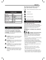
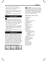
GUIDE FOR EXTENSION CORD USAGE:

Type of cable 

Up to 5 metres

From  

5 to metres  

10 metres 

Parallel 

2x 1.0mm

2

2x 1.5mm

2


 WARNING! Some spray materials contain 

chemicals known to cause cancer, birth defects or 

other reproductive harm. To reduce your exposure 

wear appropriate safety equipment such as face 

masks, gloves, and other appropriate protective 

equipment. Please review and follow the safety 

precautions on the paint container.

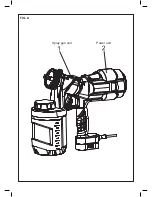
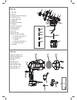
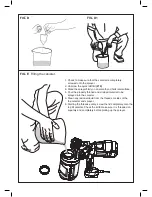
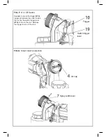
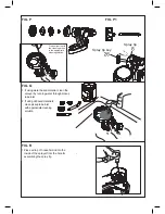
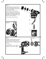
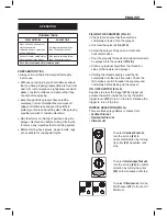
FEATURES (FIG. A, FIG. A1, FIG. A2)
1.
 Spray gun unit 

2. Power unit 

3. Tip collar

4. Air cap 

5. Nozzle (Φ1.5mm/Φ3.5mm) 

6. Y-type seal ring 

7. Spray width lever 

8. Spray tip 

9. Spray unit housing 

10. Trigger 

11. Flow control knob  

12. Quick refill lid

13. Sealing liner

14. O-ring 

15. Pickup tube 

16. Check valve assembly 

16.1 Check valve sleeve 1 

16.2 Check valve 

16.3 Spring

16.4 Check valve sleeve 2

16.5 Valve extension

17. Canister

18. Quick release lock 

19. Switch trigger lever 

20. Hanging hook 

21. Filter 

22. Filter cover 

23. Viscosity cup 

24. Cleaning needle 

25. Cleaning brush  

26. Spray tip key 

ELECTRICAL SAFETY 

EXTENSION CORD 

Summary of Contents for PLD3151S

Page 1: ...pray Gun English Assembling Use Maintenance Manual WARNING READ INSTRUCTIONS MANUAL BEFORE USING PRODUCT Assembling Use Maintenance Manual English Electric Spray Gun WARNING READ INSTRUCTIONS MANUAL B...

Page 2: ...FIG A Spray gun unit Power unit Spray gun unit Power unit FIG A...

Page 3: ...ck release lock 20 21 22 Filter 23 Filter cover 24 Viscosity cup 25 Cleaning needle 26 Spray tip key FIG A1 3 Tip collar 4 Air cap 5 Nozzle 1 5mm 3 5mm 6 Y type seal ring 7 Spray width lever 8 Spray t...

Page 4: ...wise until stop Rotate the quick release lock 19 and snap onto the hook on the edge of canister lid FIG B Aligning the pickup tube The pickup tube 15 needs to be aligned in the direction toward the fr...

Page 5: ...the lid to make sure it is threaded on squarely and completely before picking up the sprayer FIG D1 FIG D FIG D1 FIG E Filling the canister 1 Check to make sure that the canister is completely screwed...

Page 6: ...he trigger 10 trigger will actuate the switch inside the tool by the switch trigger lever 19 to turn on the tool Release the trigger to turn off the tool FIG G Smart nozzle selection Trigger Switch tr...

Page 7: ...n This is done by spraying in horizontal strips and then crossing over these strips with vertical strips FIG H Always spray from a minimum of 2 to a maximum of 12 FIG I Avoid moving your wrist FIG J A...

Page 8: ...the canister Spray the cleaning solution through the sprayer onto scrap material for 2 to 3 seconds FIG M Pour a small amount of the appropriate cleaning solution into the canister FIG K Unscrew the c...

Page 9: ...ce a drop of household oil into the inside of the sprayer from the hole for assembling the spray tip FIG P FIG P1 Spray tip key Spray tip Clean all parts with the cleaning brush in the appropriate cle...

Page 10: ...on back of the filter cover 22 and remove the filter cover 22 housing 09 Refer to Fig S1 for proper FIG S Reassemble sprayer Note Spray nozzle can only be assembled in one direction that the notch of...

Page 11: ...rty damage ENGLISH The following are explanations of important safety hazard pictorials in this manual SAVE THESE INSTRUCTIONS To reduce the risks of fire or explosion electrical shock and the injury...

Page 12: ...USE SEVERE INJURY To avoid these risks take the following preventions Keep electrical cord plug and sprayer trigger free from spray material and other liquids Never hold cord at plug connections to su...

Page 13: ...drop in line voltage resulting in loss of power and overheating If an extension cord is to be used after the cord type designation For example a designation of SJTW A would indicate that the cord woul...

Page 14: ...need to be thinned diluted before starting When thinning use the proper liquid thinner recommended on the container by the material manufacturer WARNING Do not use materials with a flashpoint higher...

Page 15: ...have gloves paper towels rags etc available for unexpected spills FILLING THE CANISTER FIG E Check to make sure that the canister is completely screwed onto the sprayer Unscrew the quick refill lid 1...

Page 16: ...ation Air cap 4 Spray Jet pattern Spray with 7 lever Initial coatings corners edges and hard to reach locations Small circular jet Vertical narrow jet for horizontal coating direction Vertical wide je...

Page 17: ...Remember that the flow control knob regulates the amount of liquid that can be sprayed Turning the flow knob clockwise increases the flow of liquid Turning the knob counterclockwise decreases the flow...

Page 18: ...th the skirt on spray unit housing 9 Refer to FIG S for proper assembly Note The spray tip must be assembled in the sprayer with the bumps on the spray tip in vertical direction Note Assemble the pick...

Page 19: ...ot be disposed of with normal day that your product needs replacement or if it is of no further use to you do not dispose of it with household waste Make this product available for separate collection...

Page 20: ...uch material being sprayed Reduce paint flow by turning flow control knob TROUBLE LITTLE OR NO MATERIAL BEING RELEASED WHAT S WRONG WHAT TO DO Spray nozzle tip clogged Clean nozzles Y type seal ring o...

Page 21: ...ace TROUBLE SPRAYER PULSATES WHAT S WRONG WHAT TO DO Air filter clogged Clean or change air filter Material in canister almost empty Refill canister Canister loose Screw canister tightly in place Quic...

Reviews: