ENGLISH
OPERATION
THINNING TABLE
SPRAY MATERIAL
RUNOUT TIME
Clear and semi- transparent
stains and sealers
Oil based primers, varnishes
and polyurethane.
No thinning required (Less
than 70 seconds runout)
Solid color water based stains
Water based or latex paints.
May require thinning (More
than 70 seconds runout)
Note: Not recommended for textured paint.
PREPARATION TIPS
> Always stir and strain the material thoroughly
before use.
> With any spraying job you should always ensure
that you have properly prepared the are free from
dust, dirt, rust and grease. Lightly pressure wash
decks or exterior surfaces and ensure that they
are dry before spraying.
> Even though HVLP sprayers have very little
overspray, it is recommended that you mask all
edges and other areas and use drop cloths to
protect your floors and anything else in the spraying
area that you wish to remain untouched.
> Skin that forms on the top of paint can clog the
sprayer. Remove skin before mixing. Strain with
to remove any impurities that could clog system.
> Before starting have gloves, paper towels, rags
etc. available for unexpected spills.
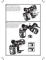
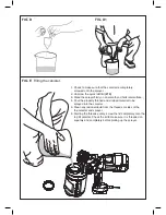
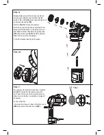
FILLING THE CANISTER (FIG. E)
> Check to make sure that the canister is
completely screwed onto the sprayer.
> Unscrew the quick refill lid (#12)
> Stand the sprayer firmly on an smooth and
horizontal surface.
> Pour the properly thinned and strained material to
be sprayed into the canister (FIG. E).
> Clean any residual liquid from the threads or
sides of the canister and sprayer.
> Starting the threads evenly, screw the lid
completely onto the top fill canister. Check the
lid to make sure it is threaded on squarely and
completely before picking up the sprayer.
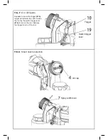
ON / OFF SWITCH (FIG. F),
Squeeze to press the trigger (#10), trigger will
actuate the switch inside the tool by the switch
trigger lever (#19) to turn on the tool. Release the
trigger to turn off the tool.
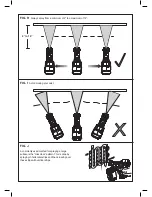
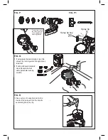
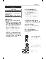
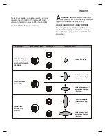
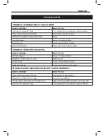
NOZZLE SELECTION (FIG. G)
There are three spray patterns to choose from:
- Vertical Flat Jet
- Horizontal Flat Jet
- Circular Jet
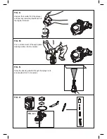
To select Vertical Flat Jet,
turn the air cap (#4) to
horizontal direction by turning
tip collar (#3) clockwise until
stop.
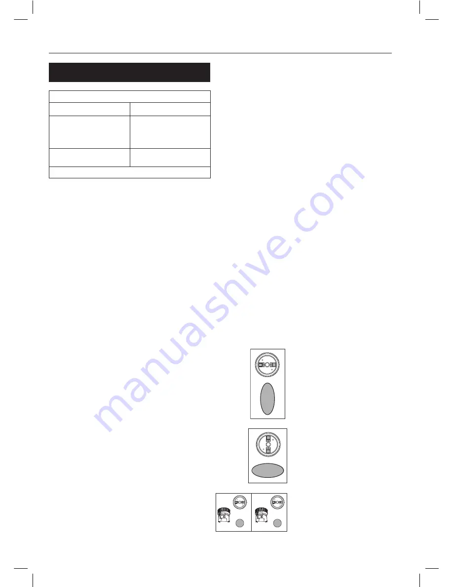
To select Horizontal Flat Jet,
turn the air cap (#4) to vertical
direction by turning tip collar
(#3) anti- clockwise until stop.
To select Circular Jet, turn he
Width Lever (#7) to the icon of
Minimum.


