background image

FCC Warning

This device complies with part 15 of the FCC rules. Operation is subject to the following two 

conditions: (1) this device may not cause harmful interference, and (2) this device must accept any 

inte rference received, including interference that may cause undesired operation.


Changes or modifications not expressly approved by the party responsible for compliance could 

void the user's authority to operate the equipment. 

NOTE: This equipment has been tested and found to comply with the limits for a Class B digital 

device, pursuant to part 15 of the FCC Rules. These limits are designed to provide reasonable 

protection against harmful interference in a residential installation. This equipment generates uses 

and can radiate radio frequency energy and, if not installed and used in accordance with the 

instructions, may cause harmful interference to radio communications. However, there is no 

guarantee that interference will not occur in a particular installation. If this equipment does cause 

harmful interferenceto radio or television reception, which can be determined by turning the 

equipment off and on, the user is encouraged to try to correct the interference by one or more of 

the following measures:

-Reorient or relocate the receiving antenna.

·Increase the separation between the equipment and receiver.

·Connect the equipment into an outlet on a circuit different from that to which the receiver is 

connected.

·Consult the dealer or an experienced radio/TV technician for help.

Radiation Exposure Statement 

This equipment complies with FCC radiation exposure limits set forth for an uncontrolled 

environment. This equipment should be installed and operated with minimum distance 20cm 

between the radiator and your body.

Summary of Contents for LKS-TM001

Page 1: ...LKS TM001 LKS TM001A LKS TM001A X LKS TM001K LKS TM001T LKS TM001W User Manual Temperature Measurement and Face Recognition Machine...

Page 2: ...troduction to the main interface 13 Login Interface 15 Setting Interface 15 User List Interface 17 Part 4 Service Platform Operations 18 Overview 18 1 1 Terminology 18 1 2 System Requirements 18 1 3 M...

Page 3: ...reasonable commercial means LKS after sales office service telephone 4006905904 office hours 8 30 a m to 9 00 p m Beijing time from Monday to Sunday No warranty under the following conditions rust or...

Page 4: ...iable for any loss or consequence caused by the misuse abuse or unauthorized modification repair or change of LKS temperature measurement products purchased by users or failure to strictly abide by th...

Page 5: ...ntification without interference Optional wired Wi FI 4G communication Multi language broadcasting Product Specifications Model LKS TM001 LKS TM001W LKS TM001A LKS TM001K LKS TM001T LKS TM001A X Opera...

Page 6: ...f human body temperature After the machine starts up the temperature measurement module needs to be preheated for 15 minutes before it can enter the normal temperature test Electrical Performance Inpu...

Page 7: ...play Normal temperature Abnormal high temperature Abnormal low temperature Application Scenarios The machine is used for quick temperature reading and face recognition in schools cinema communities su...

Page 8: ...Temperature Measurement and Face Recognition Machine User Manual 8 Installation Modes Model LKS TM001W Model LKS TM001T Wall mounted...

Page 9: ...es and hats to cover The product should be placed in an indoor environment with no wind or bright sunlight and away from air conditioning electric heating and other temperature control equipment 2 The...

Page 10: ...urement with small size easy to put simple installation fast detection speed and other characteristics Attention This installation guide is to guide the installation according to the standard installa...

Page 11: ...ver Electrical insulation tape Accessories Temperature measurement face recognition all in one machine host Body sheet metal bracket Power line 12V power adapter Cable All in one machine tool kit Base...

Page 12: ...d USB extension cable head and DC power cord head inside the bracket 2 Remove the waterproof washer corrugated elastic pad and nut from the temperature measuring all in one machine host and insert the...

Page 13: ...12V DC power cord and network cable equipment from the bottom of the temperature measuring all in one machine to start the machine f there is any problem that cannot be solved by the temperature measu...

Page 14: ...lmet detection is enabled and gray when helmet detection is disabled Time regional network time set by the system Company name can be set on the setting interface Network mode and IP address Number of...

Page 15: ...nd user list interface The initial password is 123 After successful login you can change the password on the setting interface 2 Interface elements The login procedure is not repeated here If you forg...

Page 16: ...time that is the opening time The customer can choose to enter the control time 6 Relay mode normally open normally closed 2 choose 1 This is the hardware option the sales need and the customer to det...

Page 17: ...perature calibration Use this function with caution Each hardware of temperature measurement modules has their hardware characteristics Therefore we cannot ensure that all the modules have consistent...

Page 18: ...nd has the highest management rights of the entire system System administrator When a virtual company account is created for each customer a system administrator account and password will be requested...

Page 19: ...ehensive information area Left 1 cloud platform system name Left 2 current login customer name Right 1 current login user Right 2 link for changing the password of the current user Right 3 link for ex...

Page 20: ...ator s customer on the server by default You need to add the terminal to a specific customer on the server so that the customer can see and manage the terminal under their account 1 7 Rights Managemen...

Page 21: ...ement and device registration 1 8 SaaS Management Functions 1 8 SaaS The SaaS system management menus are as follows 1 8 1 System Functions The system functions interface allows you to view all the fu...

Page 22: ...ormation based on the query conditions In the upper right corner of the main operation area the New Cust button is displayed all the addition buttons in this system are in this position which will not...

Page 23: ...no longer use the system delete their information by clicking Logout on the right of the list The users of the deleted customers can no longer log in to the system 1 9 4 Viewing Customer Rights On th...

Page 24: ...nly by the operator 1 10 1 Viewing Registered Devices Click the device registration menu on the left The registered device list is displayed on the right which can be filtered based on query condition...

Page 25: ...on the terminal Customer Management Functions The customer management functions allow you to manage the internal functions devices and personnel of the customer The functions include system managemen...

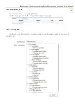
Page 26: ...ent You can add and delete roles and assign rights to roles Click the role management menu The existing role list is displayed on the right 1 11 2 1 Viewing Roles Click the role name The interface for...

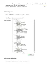
Page 27: ...e and adjust the role functions The system administrator always has all the rights in the system 1 11 2 2 Adding a Role Click the Add Role button to add a role and specify the role functions 1 11 2 3...

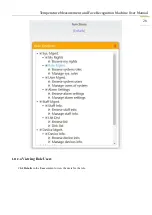
Page 28: ...Temperature Measurement and Face Recognition Machine User Manual 28 1 11 2 4 Viewing Role Users Click Details in the User column to view the users for the role...

Page 29: ...can no longer log in to the system 1 11 3 User Management You can add and delete users and assign roles to users Click the user management menu The existing user list is displayed on the right 1 11 3...

Page 30: ...e Recognition Machine User Manual 30 1 11 3 2 Adding a User Click the Add User button The Add User interface is displayed 1 11 3 3 Viewing User Functions Click Info in the Function column to view the...

Page 31: ...password click Reset Password in the User column to reset the password The reset password is 123456 1 11 4 Alarm Settings The alarm settings are used to set the alarm conditions of the system Currentl...

Page 32: ...ton The alarm settings interface is displayed Enter the alarm information and click Save 1 11 4 3 Deleting Alarm Settings Click Delete in the Operation column to delete the alarm settings that are not...

Page 33: ...wing Device Information Click the device number in the Device No column to view and modify the device details 1 12 1 2 Adding a Device Click the Add Device button enter the device information and clic...

Page 34: ...13 Staff Management You can manage the information of the personnel using the device including staff information and list distribution 1 13 1 Staff Information You can add staff modify staff informat...

Page 35: ...the staff list click the staff s photo thumbnail to view the big photo 1 13 1 3 Adding a Staff Click the Add Staff button On the staff information interface enter the staff information and click Save...

Page 36: ...ion records including automatic distribution records Click the list distribution menu All distribution records and distribution status in the current system are displayed on the right 1 13 2 1 List Re...

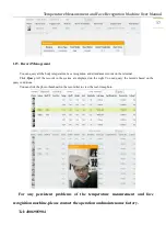
Page 37: ...he terminal Click Query All the records in the system are displayed on the right You can query the records based on the query conditions You can click the photo thumbnail in the record list to view th...

Page 38: ...ot installed and used in accordance with the instructions may cause harmful interference to radio communications However there is no guarantee that interference will not occur in a particular installa...

Reviews: