background image

Summary of Contents for ADM-2

Page 1: ...ADM i MaintenanceManual ...

Page 2: ...intain and troubleshoot the ADM 2 Interactive Display Terminal A brief description of the unit and its options are included in the manual to assist the service technician in maintaining the equipment For additional infor mation on the ADM 2 write Lear Siegler Inc 714 N Brookhurst St Anaheim CA 92803 ...

Page 3: ...5 3 5 3 8 THEORY OF OPERATION 4 4 1 4 1 1 4 1 2 4 1 3 4 1 4 4 1 5 4 1 6 4 1 7 4 1 8 4 1 9 4 1 10 4 1 11 4 1 12 4 1 13 4 1 14 4 1 15 4 2 4 2 1 4 2 2 4 2 3 4 2 4 MAIN LOGIC BOARD Clock Schematic P 2 Counters Display Generation Schematic P 2 Tristate Bus TSB Schematic P 13 Microprocessor Logic Keyboard Logic Schematic P 17 19 External Interface Logic Schematic P 20 23 Video Logic Schematic P 5 6 7 II...

Page 4: ... 5 2 5 2 5 2 5 2 5 11 5 11 5 11 5 13 5 13 5 14 5 15 5 15 5 16 6 LOGIC BOARD MICROCONTROLLER PROGRAMMING 6 1 7 MAINTENANCE 7 1 PREVENTIVE MAINTENANCE PM 7 2 ADJUSTMENTS 7 2 1 Synchronization and Drive Signals 7 2 2 Low Voltage Supply 7 2 3 Brightness 7 2 4 Video Contrast 7 2 5 Vertical Adjustments 7 2 6 Horizontal Adjustments 7 2 7 Focus Adjustment 7 2 8 Centering 7 2 9 Power Supply Adjustment 7 3 ...

Page 5: ...DM 2 OPTION DRAWINGS C l D ADM 2 SUBASSEMBLIES D 1 KEYBOARD 0 0 0 0 D 3 MONITOR 0 0 0 0 0 0 0 0 0 D 11 POWER SUPPLY 0 0 0 0 0 D 15 E ADM 2 LOGIC DIAGRAMS o 0 0 0 0 0 0 0 0 E 1 7 0 0 0 0 0 0 0 0 0 E 2 13 0 0 0 0 0 0 0 0 E 25 F ADM 2 PoCo BOARD ASSEMBLY 0 0 0 0 0 0 0 F 1 G ADM 2 CIRCUIT BOARD 0 0 0 0 0 0 0 0 G 1 iii ...

Page 6: ...er UART Block Diagram Video Logic Block Diagram Cursor Logic Block Diagram ADM 2 Back Panel View Poll Function Dialog Flow Diagram Select Function Dialog Flow Diagram Sequential Select Function Dialog Block Diagram Fast Select Function Dialog Block Diagram Broadcast Select Function Dialog Block Diagram Send Function Dialog Flow Diagram ADM 2 Microcontroller Program Example No Video Display Erratic...

Page 7: ...unction Keys with Transmitted Codes Status Displays ADM 2 Binary Codes Formatting Aids Data Editing Commands ASCII Code Cursor Positioning Block Transmission Functions Controls ADM 2 Functional Units ADM 2 Instruction Set Tristate Bus Control Display Control Utility Register Control RAM Address Control Random Access Memory Control Table of Flags Auxiliary Asynchronous Receiver Transmitter Control ...

Page 8: ...s each with 80 character posi tions providing a total display capacity of 1920 CRT DISPLAY LOGIC BOARD WITH MEMORY KEYBOARD characters per page Display fields are refreshed at a rate set by a crystal oscillator synchronously with 60 Hz input power in the standard terminal This rapid refresh rate generates flicker free images and high contrast display even in bright light The ADM 2 transmits data t...

Page 9: ...meric data All data characters and controls may be entered on the screen from the keyboard or received from a remote computer Reverse image display is auto matically enabled any time the cursor is positioned over data Display fields may be set to blink The standard ADM 2 character set contains 96 ASCII characters A complete ADM 2 standard character set is depicted in Figure 1 2 Control characters ...

Page 10: ... released the second key code cannot be transmit ted until the first depressed key has been released The keyboard can be removed from the ADM 2 display unit enclosure and placed up to five feet away Figure 1 3 illustrates the standard ADM 2 keyboard PROG ICONV MODE MODE PAGE TAB SOM BACK SET EOM PAGE t CR FWD HOME RESET NEW LINE I TAB 7 8 9 4 5 6 1 2 3 Figure 1 3 ADM 2 Keyboard 1 3 ...

Page 11: ...uit Board The ADM 2 power supply provides the main logic board with 5V DC The power supply is rated at 12 amps and contains an internal voltage regula tor current limiter and overvoltage protection The power supply is capable of supplying the display terminal functions with a load regulation of 075 The power supply is shown in Figure 1 5 OUT r 2 I 03 Rll I I REGULATOR CARD I C1 Rl R2 R3 Wl I I I 3...

Page 12: ... 2 Interactive Display Terminal is shown in Figure 1 6 The dimensions are noted in the figure Table 1 1 lists the specifications of the ADM 2 Table 1 2 lists the monitor specifications of the ADM 2 unit Figure 1 6 ADM 2 Interactive Display Terminal 1 5 ...

Page 13: ...olution TV lines 900 at 40 fl center Altitude Operates up to 10 000 feet 800 at 40 fl corner Dimensions overall l2Y2 H x 20Y2 W x 24 L Display Format Weight Standard 1920 characters 501bs 24 lines of 80 characters DISPLAY Character Set Generated 128 ASCII characters Lines of Characters 24 upper lower case numeric punctuation Characters per Line 80 control Displayed 64 ASCII characters Character Po...

Page 14: ...e for Transmission Asynchronous ASCII data keys separate unit with 5 cable Word Format Standard 10 bit code Character Control Optional 9 11 or 12 bit code Keys 68 Parity Cursor Format Keys 14 Standard Even Optional Odd fixed bit or none Numeric Keys Pad 14 Function Keys 16 DATA EDITING CONTROLS Transmission Send Cantro1 Keys Page line message print Keyboard Editing Character edit Type over insert ...

Page 15: ...es Input Power X Ray Radiation CONTROLS 60Hz 50Hz 15V DC short circuit protected 12KV DC 12 6V rms 24 watts nominal Comply to DHEW rules 42 CFR part 78 Input Connector Printed circuit board edge connector Viking number 2VK1OX 1 2 or Amphenol number 225 21031 101 Contrast 500 ohm potentiometer carbon composition appx 1 8 watt Amplitude Video low Video high 0 0 to OAV 4V 1 5V ELECTRICAL Minimum Maxi...

Page 16: ...S 232 C interface that comes with the ADM 2 The ADM 2 is equipped for standard 60 Hz 110 volt AC power 50 Hz and or 230volt AC power input are easily accommodated The monitor supply transformer power supply transformer and input voltage connections to the main logic board can be reconnected for 230 volt AC A word structure option allows the ADM 2 to transmit and receive data characters in anyone o...

Page 17: ...ty bit 0 JSTART I 2 3 4 5 6 7 Ip yl STOP ISTOP I A protect bit in the bit 8 position may be transmitted or received by the ADM 2 With this arrangement the following formats can be accommodated If bit 8 I the protect bit will be written 1 Ten or eleven unit code one or two stop bits with no parity bit J START 1 2_ _3 4 5_ L _ 6 _ _ 7 _ _8_ _I STOP Eleven or twelve unit code one or two stop bits wit...

Page 18: ...lly inspect the exterior of the enclosure for evidence of physical damage which may have occurred in shipment Check the hardware to determine if any assemblies or screws have been loosened during shipment Tighten as required Inspect for dust or foreign material which may impair electrical contact when cable connections are made Vacuum to remove any loose dirt The ADM 2 is now ready for installatio...

Page 19: ...CATED ON THE REAR OF THE UNIT f Select the transmission baud rate in accor dance with Table 2 4 Table 2 4 Transmission Baud Rate Select BAUD RATE SWITCH SETTING Thumb Wheel Type 110 7 150 6 300 5 600 4 1200 3 2400 2 4800 1 9600 0 g Select mode B block F full H half with mode select switch h Set EIA switch to the left for RS 232 C interface standard or to the right for the optional current loop int...

Page 20: ...a interface Table 2 2 lists the proper 11 connections for the optional data interface 1I is connected to the computer modem or acoustic coupler via cable The RS 232 C Extended interface is used as an auxiliary interface enhancing the standard RS 232 C capabilities of the ADM 2 This interface connects to the next terminal in line via cable connector 12 Table 2 3 lists the proper pin connections for...

Page 21: ...stallation information may be found in Appendix C 2 4 4 Word Structure To change the standard 10 unit code of the ADM 2 the asynchronous receiver transmitter chip on the main logic board must be re strapped as detailed in Appendix C The auxiliary asynchronous receiver transmitter used with a serial printer interface or the RS 232 C extended interface may be re strapped in accor dance with the data...

Page 22: ...lling interface serial printer interface 20ma current loop interface and an extended data interface for either the RS 232 C standard data interface or the 20ma current loop interface All functional blocks shown in Figure 3 1 are described in the following subsections OPERATOR INPUT SERIAL LINE_ PRINTER KEYBOARD SERIAL PRINTER INTERFACE POWER SUPPLY MAIN LOGIC BOARD WITH MEMORY CRT DISPLAY POLLING ...

Page 23: ... in a row reaches 80 indicating a full row of characters Controlling all activities in response to commands Generating the dot patterns for data displayed on the CRT Cursor display generation and cursor position control 3 3 KEYBOARD The ADM 2 keyboard contains 118 keys for alpha numeric display and control When a key is depressed it is encoded into a parallel ASCII character that appears on eight ...

Page 24: ...y 27 of the time leaving 73 of the RAM s time available for the control section functions 3 3 Main logic board data information and control commands are transferred internally between the various logic sections via an 8 bit tristate bus TSB The TSB is a bidirectional central data path bet ween all sections of the logic board The three possible states of the TSB are a State One a true condition log...

Page 25: ...ains low order 7 bits of the RAM address accessible to the tristate bus column Contains high order 5 bits of the RAM address accessible to the tristate bus row Enable to transmitter holding registerin UART Input bit from printer terminal 13 Used to transfer constants from ROMtotristate bus Holding register for character position count Register that contains present character posi tion horizontal F...

Page 26: ... of the ADM 2 The program mode is cleared by an ESC X or ESC U command or by depressing the BREAK key on the keyboard 3 5 3 7 2 Polling Interface The ADM 2 may be used as a polling terminal in a multiprint communications network In this mode all message transmission to the polling terminal is controlled by the network control center The network control center transmits a header sequence to all ter...

Page 27: ... position on the screen The SaM STX code symbol and the EOM ETX code symbol are entered on the screen by use of the SOM EOM key with and without shift respectively 3 6 In polling operation as in normal ADM 2 opera tion control codes may be written by preceding the control code by ESC ESC ETX will cause the ETX to be written to the screen rather than being interpreted as End of Text Sending Data Wh...

Page 28: ...erminal to the idle state 3 7 Sequential Select The Sequential Select function sequentially address es a number of terminals with a single extended header All addressed terminals that are not busy will receive the same message The header sequence is EOT A1AI r A2A2 r s Note that the last terminal is addressed with the Fast Select function which is always followed by the sequence STX text ETX LRC a...

Page 29: ...r or not an error was detected and then disconnect 3 8 3 7 3 Additional Data Interfaces The function of the standard RS 232 C interface is to provide a means of communicating between the transmission facilities and the computer Not all devices use this method of communication The ADM 2 has an optional 20ma current loop data interface available to allow the terminal to communicate with devices usin...

Page 30: ...e shown in Figure 4 3 4 1 2 Counters Display Generation Schematic P 2 Display generation in the ADM 2 is provided by a series of counters Dot Position Character Posi tion Character Height and Character Line counters are used to produce on the CRT a 5 x 7 char acter and a 7 x 9 cursor Counter operation is started by a clocking pulse from the oscillator The dot position counter is a divide by 7 type...

Page 31: ...NTAL DRIVE lOGIC VERTICAL DRIVE CLOCK TIMING LOGIC CONTROL MiCRO PROCESSOR s x I O INTERFACE INTERFACE SIGNALS J H LOGIC TO RR 8 s C I m J l KEYBOARD RECEIVER lOGIC WRITE DATA REGISTER REFRESH lOGIC FROM KEYBOARD ROM CONTROL MEM ALL CLOCKS TIMING SIGNALS REQUIRED ARE DISTRIBUTED THROUGHOUT Figure 4 1 ADM 2 Logic Board Block Diagram ...

Page 32: ...IoI j Oti C l u a I N a s 0 CfS I w te 0 l 0 U 1l 1l 0 te 0 li 0 JQ l S CHARACTER POSITION CENTER 104 CPC 8 BITS CHARACTER HEIGHT COUNTER 11 ClC 4 BITS ...

Page 33: ...son Circuit Schematic P 18 Com parison logic is used to compare the TSB with the MACC and literal register 7 or 8 bits or the NULL code The comparator logic re ceives its input signals from the MACC MACCx and literal register LITx The signals are sent through a 2 1 selector which sends only the enabled signals to the compa rator circuit Command decode logic signals CMDx enable the comparator and o...

Page 34: ...R I LITERAL S MARGIN REGISTER T REGISTER A T E LRC REGISTER B CURSOR POSITION U STORAGE S REGISTER TR1STATE BUS A CONDITION r MEMORY ADDRESS REGISTER A COMPARATOR WRITE DATA REGISTER KEYBOARD DATA A READ DATA INTERFACE v Kr REGISTER i INDICATOR REGISTER Figure 4 3 Tristate Bus and Elements that Use It 4 5 ...

Page 35: ...polling option has been installed and the terminal is oper ating in the polling mode If the character and data line do compare a logic 0 is output by the circuit The LRC register is capable of being loaded from the TSB and outputting to the TSB Keyboard Schematic P 19 Keyboard in puts enter the logic board at J6 The J6 terminal output signals KDl 8 are sent to 4 6 TSB drivers which are enabled by ...

Page 36: ...EGISTER PC JUMP LOGIC PROGRAM COUNTER CMDEC CONDITION CIRCUIT CONTROL MEMORY OPTION COND LOGIC MAC COND LOGIC INTERFACE GENERAL CONC MUX STATUS REGISTER STATUS MUX TSB CONTROL Figure 4 4 Microprocessor Logic Block Diagram TSB MUX CONDITION ...

Page 37: ... signal CONDB is input to the multi condition line schematic P 8 4 8 along with the other condition checks The numerous gates filter into the decoder and the decoder s output is controlled by the status of the tested condition The program continues according to the directions received from the condition decoder output Literal Register Schematic P 13 The literal register is loaded from the control ...

Page 38: ...nchronous Transmitter Receiver chip shown on schematic P 20 labeled Dl and D3 to interface between a serial data interface and the parallel ADM 2 control section 4 9 Baud Rate Select Schematic P 21 Baud rates Le transmission rates are user select able from 110 to 9600 baud A switch in the rear of the unit selects the desired baud rate switch settings are described in Section 2 and listed on the up...

Page 39: ...a onto the UART The UART chip in the optional printer I O channel works the same way as the DART chip in the stan dard I O channel The difference is in the circuitry used to support the DART chip As the printer can receive but not transmit data only one way communication is required The TSB is connected to the printer channel for loading the DART only TSB bits TSBI 8 provide the parallel data word...

Page 40: ...age 22 the data received from the computer is transferred on to the extension port via pin 3 20ma Current Loop Interface Schematic P 22 current loop transmitter from the ADM 2 One leg of the current loop may be tied through a resistor to 20V DC to create a current source On the 13 main logic board switch C9 1 closed gives the user the ability to inhibit RTS CA until CTS CB equals one Switch C9 2 c...

Page 41: ... of the character The status of the parity verification cir cuit appears on this line if a low level input voltage VIL is applied to the STATUS FLAGS DISCONNECT pin 16 control line Wired OR capability is provided on this line allowing PE lines from other arrays to be OR tied A high level output voltage VOH on this line under the conditions above indicates a PARITY ERROR in the received parity bit ...

Page 42: ... VIH applied to this pin disconnects the PE FE OE DR and THRE circuit outputs This clock is sixteen 16 times faster than the desired receiver shift rate A low level input voltage VIL applied to this line resets the DR line A high level output voltage VOH indi cates that an entire character has been received and transferred to the RECEIV ER HOLDING REGISTER Serial input data received on this line e...

Page 43: ...vel output voltage VOR on this line indicates that the TRANSMIT TER REGISTER has completed serial transmission of a full character including STOP bites It remains at this level until the start of transmission of the next character The contents of the TRANSMITTER REGISTER START bit DATA bits PARITY bit and STOP bit are serially shifted out on this line This line will remain at a high level output v...

Page 44: ... cuits PI will when a high level input voltage VIH is applied also clamp the PE line pin 13 to a low level output voltage VOL This line selects the number of STOP bits generated after the PARITY bit during transmission A high level input voltage VIH on this line selects two STOP bits and a low level input voltage VIL selects a single STOP bit These two lines select the character length to be 5 6 7...

Page 45: ... in Section 1 Figure 1 2 For each line displayed the character generator must receive all 80 characters seven times It must gen erate seven lines of video pulses one for each raster sweep The raster count lines CHC1 2 4 8 inform the character generator which sweep is currently taking place The character generator repeats the above operation 24 times once for each screen line inserting the necessar...

Page 46: ... BIT SCREEN REGISTER BLINK BLANK FIELD DECODE PROTECTED FIELD DETECTOR TO MONITOR INDICATOR REGISTER INDICATOR MULTIPLEXER CURSOR GENERATION MONITOR DRIVE GENER ATOR HD VS f TO MONITOR TIMING AND SYNC CIRCUITS Figure 4 6 Video Logic Block Diagram ...

Page 47: ...URSOR POSITION TOTSB STORAGE REGISTER I FROM MAC ADDR CHARACTER VIDEO VIDEO CURSOR VIDEO 7 BITS GENERATOR 5 BITS SERIALIZER f GENERATION f DRIVER eLl L 1 1 CURSOR COMPARATOR Figure 4 7 Cursor Logic Block Diagram ...

Page 48: ...is applied to the same selection circuit as the blink bit for determining its condition before it is input to the video shift register 4 19 Flip flop K4 P 6 sets the save blink field SAVBLKFLD and save blank field SAVSUPFLD Flip flop K5 P 6 sets the set blink field BLK FLD and set blank suppress field SUPFLD status 4 1 8 Data Memory Address Logic Schematic P 3 The memory address register MACe and ...

Page 49: ...e only time the gate F3 is true 4 1 13 Optional Timeout Logic Schematic P 17 An optional timer is available for command decod ing and noting a status condition The output COND TIME signal is applied to the condition input logic This option is useful for preventing a system hang up and controlling the program counter when a timeout occurs 4 20 4 1 14 Polling Option Logic Schematic P 17 The polling ...

Page 50: ...tical oscillator is synchronized externally to the vertical interval from the vertical drive pulse at R113 At the time of the vertical interval an ex ternal negative pulse is applied through R113 CI04 and CR101 to the gate of Q102 causing the firing level of the unijunction to decrease The sawtooth voltage at the anode of Q102 is di rectly coupled to the base of QI03 QI03 is a driver amplifier and...

Page 51: ... pulse is developed by the yoke s inductance and the primary of T2 The peak magnetic energy which was stored in the yoke during scan time is then transferred to C109 and the yoke s distributed capacity During this cycle the beam is returned to the center of the screen The distributed capacity now discharges into the yoke and induces a current in a direction opposite to the current of the previous ...

Page 52: ...evel R20l and C20l provide additional filtering of the rectified DC voltage 4 23 Operation of this regulator may be better under stood by assuming that a certain operation condi tion has caused the output voltage to increase above normal This positive increase of voltage is transferred to the base of Q202 where it is com pared to the zener voltage of VR20 1 The increase of forward bias of Q202 cau...

Page 53: ...e back panel This switch controls all power to the ADM 2 Placing the switch in the ON position will reset all ADM 2 circuitry position the cursor at HOME and clear the display mem ory to unprotected space codes 5 1 2 Mode Selector Switch The Mode Selector Switch is located on the bottom left side of the back panel The Mode Selector Switch is a three position switch that selects full F or half H du...

Page 54: ...rd is designed with key rollover protection Le if a key is depressed before a previously depressed key is released the second key code cannot be transmitted until release of the first key ESC ESC disables all keyboard functions except RESET enables the keyboard and re stores keyboard control The keyboard contains the following functional keys Upper case Numeric Special characters Special character...

Page 55: ... See below or CTRL SHIFT DISPLAYED ASCII CODE CHARACTER KEYS USED NULL SOH A CTRL A STX SHIFT SOM EOM CTRL B ETX SOM EOM CTRL C EOT 12 CTRL D ENQ E CTRL E ACK E CTRL F BEEP Q CTRL G BS CTRL H HT TAB CTRL I LF LF CTRL J VT 1 t CTRL K FF t CTRL L CR El RETURN CR CTRL M SO A CTRL N SI v CTRL O DLE Q CTRL P DCI 1 CTRL Q DC2 1 CTRL R DC3 1 CTRL S DC4 4 CTRL T NAK l CTRL U SYN Y CTRL V ETB W CTRL W CAN ...

Page 56: ...URN CR LF NEW LINE TAB SET TAB BACKTAB 4 Increment Up Down Left Right t TERMINAL CONTROL 1 Reset 2 Break 3 Clear Screen or Foreground to a Spaces b Null Codes 4 Audible Tone 5 Display Extended Memory Control Optional DATA TRANSMISSION CONTROL I Transmission Mode 2 Transmission Initiation Block Mode 3 Send to Printer 4 Transmitted Text Delimiters 5 Special Functions 5 4 RESET BREAK CLEAR SP CLEAR N...

Page 57: ...68 DCI 48 DCI 68 10 FlO DCI 49 DCI 69 DCI 49 DCI 69 11 FII DCI 4A DCI 6A DCI 4A DCI 6A 12 Fl2 DCI 4B DCI 6B DCI 4B DCI 6B 13 Fl3 DCI 4C DCI 6C DCI 4C DCI 6C 14 F14 DCl 4D DCl 6D DCl 4D DCl 6D 15 F15 DCl 4E DCl 6E DCl 4E DCl 6E 16 F16 DCI 4F DCI 6F DCI 4F DCI 6F SEND 17 PAGE ESC 35 ESC 37 ESC 35 ESC 37 SEND 18 LINE ESC 34 ESC 36 ESC 34 ESC 36 SEND 19 MESSAGE ESC 53 ESC 73 ESC 53 ESC 73 20 PRINT ESC...

Page 58: ...SC 54 ESC 74 ESC 54 ESC 74 PAGE 29 ERASE ESC 59 ESC 79 ESC 59 ESC 79 WRITE 30 PROT ESC 28 ESC 29 ESC 28 ESC 29 PROT 31 MODE ESC 26 ESC 27 ESC 26 ESC 27 PROG 32 MODE ESC 55 ESC 75 ESC 55 ESC 75 CONY 33 MODE ESC 42 ESC 43 ESC 42 ESC 43 34 2D 2D 2D 2D 35 TAB 09 09 09 09 36 1 31 21 31 21 37 2 32 22 32 22 38 3 it 33 23 33 23 39 4 34 24 34 24 40 5 35 25 35 25 41 6 36 26 36 26 42 7 37 27 37 27 43 8 38 28...

Page 59: ...ESC 6A TAB 52 SET ESC 56 ESC 76 ESC 56 ESC 76 SOM 53 EOM ESC 03 ESC 02 ESC 03 ESC 02 54 7 37 37 37 37 55 8 38 38 38 38 56 9 39 39 39 39 57 CTRL 58 Q 71 51 11 11 59 W 77 57 17 17 60 E 65 45 05 05 61 R 72 52 12 12 62 T 74 54 14 14 63 Y 79 59 19 19 64 U 75 55 15 15 65 I 69 49 09 09 66 0 6F 4F OF OF 67 P 70 50 10 10 68 5B 7B IB IB 69 50 7D 10 10 70 ESC IB IB IB IB BACK TAB 71 TAB ESC 69 ESC 49 ESC 69 ...

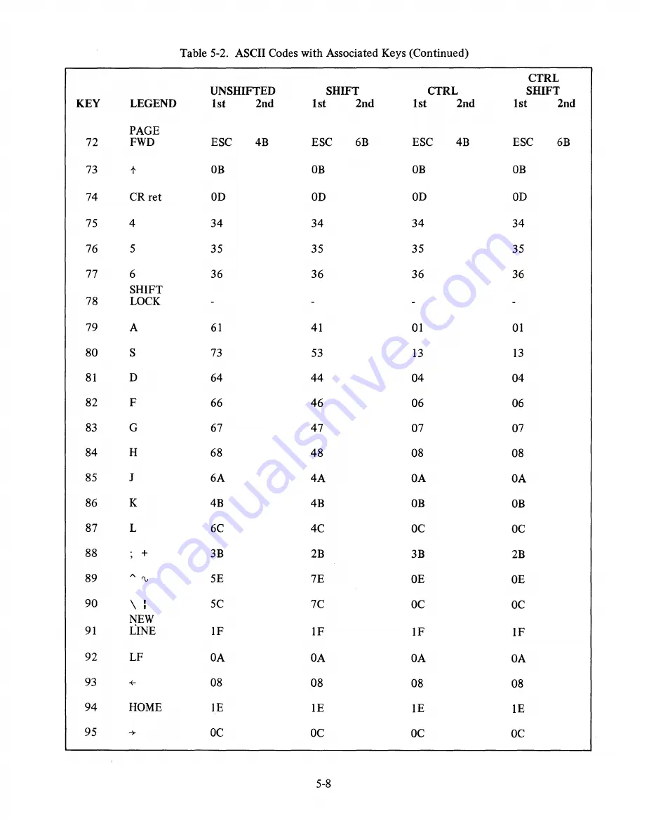
Page 60: ...OB 74 CRret OD OD OD OD 75 4 34 34 34 34 76 5 35 35 35 35 77 6 36 36 36 36 SHIFT 78 LOCK 79 A 61 41 01 01 80 S 73 53 13 13 81 D 64 44 04 04 82 F 66 46 06 06 83 G 67 47 07 07 84 H 68 48 08 08 85 J 6A 4A OA OA 86 K 4B 4B OB OB 87 L 6C 4C OC OC 88 3B 2B 3B 2B 89 V 5E 7E OE OE 90 5C 7C OC OC NEW 91 LINE IF IF IF IF 92 LF OA OA OA OA 93 08 08 08 08 94 HOME IE IE IE IE 95 OC OC OC OC 5 8 ...

Page 61: ...5 9 ...

Page 62: ...OH K CR SOH k CR F13 SOH L CR SOH 1 CR F14 SOH M CR SOH m CR F15 SOH N CR SOH n CR F16 SOH 0 CR SOH 0 CR Table 5 4 Status Displays STATUS CONDITION KEY SET STATUS CLEAR STATUS INDICATOR 1 Keyboard Lock ESC ESC 2 ADM l Mode ESC ESC 3 Unassigned ESC c ESC b 4 Unassigned ESC e ESC d 5 Unassigned ESC g ESC f 6 Message Waiting ESC ESC PROG 7 Program Mode MODE ESC U ESC X PAGE 8 Page Edit Mode EDIT ESC ...

Page 63: ... enables the ADM 2 under microprogram control to inter pret the next character or string of characters as special control instructions These sequences are used for a Keyboard enabling disabling b Formatting i e field protection field secur ity and field blinking c Data transmission control character line page or message d Data editing control e Absolute cursor addressing reading f Selecting specia...

Page 64: ...ETPGM J STATUS 2 CLR PGM 0101 ENQ NAK 5 E U e u MODE PAGE LINE MODE ON MODE SET SEND ALL SETTAB J STATUS 3 0110 ACK SYN 6 F V f v PROTM LINE COLUMN OFF J CLEAR SEND ALL DELETE STATUS 3 0111 BEEP ETB 7 G W 9 w PROTM PAGE CHAR ON CLEAR CLEAR PGM 1000 BS CAN 8 H X h x WPROT MODE SKIP SET BACK ERASE WTAB WPAGE TO 1001 HT EM 9 I Y I Y WPROT TAB PAGE SKIP NULL j CLEAR ALL CLEAR FG L J PAGE L J 1010 LF S...

Page 65: ...a Editing The ADM 2 has been designed with complete data editing capabilities Editing may be done from either the keyboard or computer Table 5 7 sum marizes the data editing operations available For detailed information on ADM 2 data editing opera tions refer to the ADM 2 Operator s Manual Table 5 7 Data Editing Commands I i 1 OPERATION KEYBOARD CONTROL COMPUTER CODES Clear Foreground to Spaces CL...

Page 66: ...ons down for Y or to the right for X use ASCII codes in ascending order these codes are shown in Table 5 8 Table 5 8 ASCII Code Cursor Positioning ASCII ASCII ASCII XorY CODE X CODE X CODE 1 SPACE 28 55 V 2 29 56 W 3 30 57 X 4 31 58 Y 5 32 59 Z 6 33 60 7 34 A 61 8 35 B 62 9 36 C 63 A 10 37 D 64 11 38 E 65 12 39 F 66 a 13 40 G 67 b 14 41 H 68 c 15 42 I 69 d 16 43 J 70 e 17 0 44 K 71 f 18 1 45 L 72 ...

Page 67: ... Fl through F16 none Defined Message Foreground Send Message ESC S Defined Message All Shift Send Message ESC s Line Foreground Send Line ESC 4 Line All Shift Send Line ESC 6 Page Foreground Send Page ESC 5 Page All Shift Send Page ESC 7 Cursor Coordinates See Note ESC Not available to operator must be requested by computer 5 4 OPERATOR PROCEDURES POLLING MODE Information to be sent by the termina...

Page 68: ...ers space through DEL c A function code character which is one of the following P POL q Select r Sequential Select s Fast Select t Broadcast Select NOTE IF EOT ETX STX ACK NAK OR ANY CONTROL CHARACTER IS RE QUIRED ON THE SCREEN IT MUST BE PRECEDED BY AN ESC Function keys F 1 through F 16 will send four characters when the ADM 2 is polled The char acter sequence is SOH text character ETX LRC Note t...

Page 69: ...ED AT CENTER CONTROL CENTER I EDT A A p ENQ l f EDT NAK ACK l TERMINAL NO MESSAGE WAITING I r Er DISCONNECT MESSAGE WAITING STX TEXT ETX LRC J DISCONNECT RETURNS TO WAIT TO BE POLLED STATUS Figure 5 2 Poll Function Dialog Flow Diagram 5 17 ...

Page 70: ...I ACK OR DISCONNECT I I I IF EOT IN I MESSAGE TERMINAL I DISCONNECTS I STX TEXT ETX LRC l I I I ERROR IN NO ERROR MESSAGE I I I I NAK ACK NO OFTRIESPROGRAMME _T_C_E_N_T_E_R _ EOT DISCONNECT DISCONNECT Figure 5 3 Select Function Dialog Flow Diagram 5 18 ...

Page 71: ...TERMINAL An _ A _ r I AnAn s An BUSY D ISCONN ECT NOT BUSY l WAIT FOR STX BUSY OR NOT WAIT FOR STX RECEIVE STX TEXT ETX I LRC l RECEIVE DISCONNECT NO OF TRIES PROGRAMMED I ERROR IN MESSAGE J NAK NO ERROR I ACK DISCONNECT Figure 5 4 Sequential Select Function Dialog Block Diagram 5 19 ...

Page 72: ...RMINAL I I EaT I A A I 5 I I BUSY OR I NOT I I WAIT FOR STX STX I TEXT ETX I I LRC I l 1I I I I ERROR IN NO ERROR I MESrGEI I I NAK ACK NO OF TRIES PROGRAMMED DISCONNECT Figure 5 5 Fast Select Function Dialog Block Diagram 5 20 ...

Page 73: ...LS TERMINAL I I A 1 THROUGH An 1 I An EOT A If A A 1A 1 I t IA 1 I I A2A 2 IA BUSY OR NOT I BUSY OR NOT t 2 I WAIT FOR STX I WAIT FOR STX I AnAn S I An STX TEXT ETX LRC l DISCONNECT Figure 5 6 Broadcast Select Function Dialog Block Diagram 5 21 ...

Page 74: ...CONTROL CENTER l EOT A A v w x y orz ENQ TERMINAL STX TEXT ETX LRC EDT NAK ACK L 1 EaT t DISCONNECT NO OF TRIES PROGRAMMED AWAITS POLLING Figure 5 7 Send Function Dialog Flow Diagram 5 22 ...

Page 75: ... UNIT UNIT MNEMONIC RCV From External Serial Source via UART Receiver KEY From Keyboard CPR From Cursor position row register CPC From Cursor position character register LIT From To Eight bit literal register RDR From Random access page buffer via the Read Data Register WDR To Random access page buffer via the Write Data Register LRC From To Modulo 2 adder and accumulator 7 bits ADD From Switch 8 ...

Page 76: ...202 JFC TSB3 322 JTC OPTI 045 CLRIND 203 JFC TSB4 330 JTC RDR 046 LOACMD 204 JFC TS B5 331 JTC RPE 051 LOA CNTR 205 JFC TSB6 332 JTC RFE 052 INC CNTR 206 JFC TSB7 333 JTC ROE 053 DEC CNTR 207 JFC TSB8 334 JTC THRE 054 SET TIME 210 JFC KEYSTR 335 JTC CTS 055 SET BIN 213 JFC CALL 336 JTC TRE 056 CLR RTSEN 214 JFC RTN 337 JTC NRST OPT2 057 SET RTSEN 220 JFC OFLO 340 JTCPROTM 060 CLR STBI 221 JFCMAC C...

Page 77: ...to CPC TSB CPR 165 Set the TSB contents equal to CPR TSB LRC 166 Set the TSB contents equal to LRC TSB ADD 170 Set the TSB contents equal to ADD TSB INPUT 172 Set the TSB contents equal to INPUT TSB MAR 173 Set the TSB contents equal to MAR TSB IND 174 Set the TSB contents equal to IND TSB CNTR 175 Set the TSB contents equal to CNTR Display control and utility register control instructions are lis...

Page 78: ...unter to value on tristate bus LOAMACR 031 Set row counter to value on tristate bus LOA CPR 027 Sets contents of CPC and CPR equal to current con tents of MACC and MACR respectively SETMACC 022 Set character counter to right margin SETMACR 032 Set row counter to bottom row INC MACC 023 Move character counter right one position INC MACR 033 Move row counter down one line DEC MACC 024 Move character...

Page 79: ...ntly written into the RAM CLR WPROT 007 Clears the write protect bit on all words subsequently written into the RAM SETPROTM 016 Set the PROTM This status bit is used as a global condition by the program to disable the overwriting of any characters in the RAM for which the WPROT bit is set CLRPROTM 017 Clear the PROTM This global condition enables the overwriting of write protected characters Flag...

Page 80: ...st to Send BIN 055 Automatic Modifies LOA LOA MACR instructions after 1 cycle In addition to the main transmitter receiver inter face normally associated with the computer an additional transmitter receiver interface is accom modated by the instructions listed in Table 6 9 Table 6 9 Auxiliary Asynchronous Receiver Transmitter Control MNEMONIC D1 2 D 1 0 DESCRIPTION SEL ARTO 120 Selects main receiv...

Page 81: ...e same page are facilitated by the CALL and RTN conditions as follows JFCCALL JFC RTN 213 214 Causes contents of the program counter to be trans ferred to CNTR prior to transfer of control Causes contents of CNTR to replace contents of program counter LLL is ignored CNTR must be incremented prior to this operation Table 6 11 is a list of miscellaneous control instructions in the ADM 2 instruction ...

Page 82: ...Bit 4 TSB5 04 Tristate Bus Bit 5 TSB6 05 Tristate Bus Bit 6 TSB7 06 Tristate Bus Bit 7 TSB8 07 Tristate Bus Bit 8 STBI 60 Status Bit 1 STB2 61 Status Bit 2 STB3 62 Status Bit 3 STB4 63 Status Bit 4 STB5 64 Status Bit 5 STB6 65 Status Bit 6 STB7 66 Status Bit 7 STB8 67 Status Bit 8 KEYSTER 10 Keyboard strobe OFLO 20 MACC MACR overflow or underflow MAC CPR 21 Set if MACR equals CPR OPTI 22 Wire stra...

Page 83: ...r next character Clear to send asynchronous transmission remote device ready for transmission TRE 36 RESET OPT2 37 INTIN 42 KEYST2 47 RESET 44 FDX 46 MACC 50 NULL 51 LIT7 52 LIT8 53 Transmitter register empty indicator Reset by OPT2 Strap Extended memory option Second key strobe true when depressed key is a control function Reset key also used with extended memory Full duplex conversational mode T...

Page 84: ... SELARTO 0 14 36 370 0 ENA CUR 0 15 234 380 0 JFC THRE IDLE20 0 16 22 0 17 236 390 0 JFC TRE IDLE20 0 20 22 0 21 122 400 0 CLR RTSO 0 22 222 410 IDLE20 JFC OPT1 IDLE30 0 23 26 0 24 105 420 0 JMP POLIDLE 0 25 0 0 26 365 440 IDLE30 JTC STB6 PRINTINGO 0 27 114 0 30 330 450 0 JTC RDR RECEIVE 0 31 165 0 32 310 460 IDLE35 JTC KEYSTR IDLE40 0 33 50 0 34 337 470 0 JTC NRST IDLE 0 35 7 0 36 60 480 KRESET C...

Page 85: ...60 IDLE60 LOA LIT 33 0 72 33 0 73 175 670 0 TSB CNTR 0 74 352 680 0 JTC LIT7 IDLE70 0 75 100 0 76 101 690 0 JMP DATACHAR 0 77 0 0 100 61 700 IDLE70 SET STB1 0 101 5 710 0 LOA WDR 0 102 100 720 0 JMP IDLE 0 103 0 104 15 730 RESET10 SET BLOCK 0 105 320 740 0 JTC OFLO RESET20 0 106 107 0 107 156 750 RESET20 CLR LRC 0 110 166 760 0 TSB LRC 0 III 42 770 0 LOA MAR 0 112 100 780 0 JMP CLEAR08 0 113 255 0...

Page 86: ...tage can be monitored at the junction of Rl14 and R130 7 1 Usual video polarity produces white characters on a black background The brightness control on the rear of the terminal should be adjusted to a point where the white raster is just extinguished The CRT will then be at its cutoff point A maximum contrast ratio can be obtained when a video signal is applied 7 2 4 Video Contrast Q101 on the m...

Page 87: ...he ring magnets should not be used to offset the raster from its nominal center position because it would degrade the resolution of the display 7 2 If the picture is tilted rotate the entire yoke 7 2 9 Power Supply Adjustment The separate sV power supply is not normally adjusted unless corrective maintenance is per formed The adjustments for the 5V power supply are in Section 7 5 7 3 CORRECTIVE MA...

Page 88: ...Siegler does not recommend individual com ponent replacement on any printed circuit board Instead the factory should be contacted relative to availability of special test equipment or factory rebuilt and tested replacement assemblies 7 4 5 Monitor Logic Board a Remove the seven connectors shown in Figure 7 8 b Remove the three grounds shown in Figure 7 8 b Remove plugs 14 and 15 located in the lef...

Page 89: ...the same operation as when the error or problem first occurred f Record the symptoms cause and module sub assembly or component that was re placed or repaired This can be used for future reference 7 5 1 Fault Isolation The ADM 2 is divided into four main parts logic board keyboard power supply and monitor Each of these parts performs a function in the ADM 2 By analyzing the failure carefully the p...

Page 90: ...TORS PROPERLY SEATED CONTRAST BRIGHTNESS CONTROLS UP REPLACE MONITOR NO NO NO NOTE REFER TO FIGURE 7 4 FOR TEST POINT DATA REPLACE SUP REPLACE LOGIC BOARD REPLACE LOGIC BOARD Figure 7 1 No Video Display Erratic Video Flow Chart 7 5 ...

Page 91: ...NO RECONFIGURE NO RECONFIGURE YES YES NO RECONFIGURE YES CHECK MODEM COMPUTER INTERFACE NO REPLACE LOGIC BOARD Figure 7 2 I O Problems Flow Chart 7 6 ...

Page 92: ...KEYBOARD CONNECTOR PROPERLY SEATED TERMINAL TO BLOCK MODE YES REPLACE LOGIC BOARD NO NOTE REFER TO FIGURE 7 4 FOR TEST POINT DATA REPLACE KEYBOARD Figure 7 3 No Characters on Screen Flow Chart 7 7 ...

Page 93: ...ST POINT 3 16 6us HORIZONTAL DRIVE CONNECTOR J 4 PIN 8 VERTICAL DRIVE CONNECTOR J 4 PIN 9 75V OV 1 I 1 2ms 1 TEST POI NT 4 SVol OV TEST POI NT 5 VIDEO SIGNAL SIGNAL WILL VARY W DATA CONNECTOR J 4 PIN 4 KEYSTROBE SIGNAL SIGNAL IS TRUE WHILE KEY DEPRESSED CONNECTOR J 6 PIN 6 Figure 7 4 Test Point Data 7 8 ...

Page 94: ...r Troubleshooting Hints The high voltage for the monitor is generated from its own self contained power supply Additionally the monitor assembly includes its own low voltage 15V DC power supply CAUTION DISCHARGE HIGH VOLTAGE BEFORE ATTEMPTING TO REMOVE OR RE PLACE THE MONITOR ASSEMBLY Table 7 2 is a guide to common monitor problems Figure 7 6 shows important monitor waveforms Figure 7 7 shows the ...

Page 95: ...0101 8 2 5 Vp p 0103 8 4 5V p p H 1 0105 8 3V p p WAVEFORMS VI CATHODE 20V p p 0104 8 1 2V P P QI05 C 30V p p Figure 7 6 Monitor Voltage Wavefonns 7 10 CRIOI ANODE 3V P P QI04 C 45V P P QI06 C 170V p p ...

Page 96: ...ISPLAY OUTPUT I f v 1 4 1 5V HIGH VERTICAL 300 US MI N j I DR IVE 1 4 MS MAX 0 4 V _ 0 0 J 1586 MS MIN I LOW I 4 21 28 MS MAX I V j t4 il 5V 1 HIGH VERTICAL 900 US _ VIDEO BLANKING NOMINAL INFORMATION 0 4 V LOW 0 0 1 VERTICAL J I 4 BLANKING TIME Figure 7 7 Input Signal Fonnat NOTES 1 The leading edges of Drive and Blanking wavefonns must start at time II Nominal Blanking times should be observed 2...

Page 97: ... l I N a o 2 o 1 o 1 n E 1 RU9 9 MAIN CHASS S BOARD I I I I I I I I I I I I I I I I I I I I I I I I I I I I I I I I I I J it J KEYWAY FOR CONNECTOR POLARIZATION ...

Page 98: ...nector cable Improper signals on terminals 4 and 5 indicate trouble with the main logic board Operate the keyboard and note if signal levels are present at terminals of connector J6 if signals are not present examine keyboard assembly for obvious faults Either repair or replace keyboard assembly Keyboard output levels are compatible with TTL circuits logic 1 is 2 6V or greater at lOrna and logic 0...

Page 99: ... I O J4 1 Brightness 2 Brightness 3 Brightness 4 Contrast 5 Chassis Ground 6 Video Vertical Ground 7 Horizontal Ground 8 Horizontal Drive 9 Vertical Drive Logic Board Power J5 1 AC Feed 32 volts rIllS 2 AC Feed 3 Equipment Ground 4 Speaker 5 Speaker 6 DC Feed 5 volts Keyboard I O J6 1 CTRL 2 RESET 3 4 BIT 8 5 BIT 6 6 BIT4 7 BIT 2 8 BIT 1 9 BIT 3 10 BIT 5 11 BIT 7 12 PAGE EDIT 13 SHIFT 14 BREAK 15 ...

Page 100: ...IJ U 0 I 16 17 I IS 14 II II 11 It I 7 r 4l I z L Bl 4C t ET SH 4 L lftli Wr 1f1 lcr I V 51 1 WITH 13tJJ4 J W INST tU L REr ATO INhltJ 1 WH PE fl Z9374 II JS r L I j Figure 7 9 Main Logic Board Assembly with Terminal Locations ...

Page 101: ...ollowing procedures should be followed a Prepare the following information 1 Model type of equipment to be returned 2 Serial number 3 Reported symptom if failure 4 Type of modification or option to be installed if applicable 7 16 b Please call 714 774 1010 ext 371 or write to Lear Siegler Inc EID 714 N Brookhurst St Anaheim CA 92803 Attn Customer Service Please state that you would like a Return G...

Page 102: ...APPENDIX A ADM 2 PARTS LIST A I ...

Page 103: ...93 128349 104 128349 506 128349 805 128518 101 128518 103 128518 104 128518 225 128533 102 128533 103 128533 151 128533 183 128533 203 128533 221 128533 271 128533 301 128533 393 128533 472 128533 512 128533 513 128533 621 QUANTITY 2 1 3 14 2 1 1 2 22 2 3 1 6 2 9 2 13 1 1 3 17 5 13 1 6 1 2 6 5 1 16 4 12 1 1 10 6 6 1 4 1 8 1 3 12 3 8 6 1 1 1 1 1 1 1 8 3 1 2 A 2 DESCRIPTION IC IC IC IC IC IC IC IC I...

Page 104: ...SISTOR RESISTOR RESISTOR BRACKET IC IC IC IC IC IC CHARACTER GENERATOR ROM ROM CAP CAP CAP TE1059 5 BOARD PC BRACKET RESISTOR RESISTOR EB9115 NETWORK RESISTOR POT lOOK YQ8383 POT 500 YQ8384 SOCKET CA 14S 10SD SOCKET CA16S10SD SOCKET CA24S 10SD SOCKET CA28S 10SD SOCKET CA40S 10SD SOCKET JACK 17 893 SOCKET SHORT PIN 17 1208 CONNECTOR 17 1209 SWITCH MSS 2250R SWITCH MSS4350 SWITCH 435640 2 SWITCH 435...

Page 105: ...J5504 129350 ADM 2 FINAL ASSY COMPONENT NO 128565 25 128565 26 128565 5 128565 6 128565 8 128565 9 128587 1 128595 3 129302 2 129305 13 129318 1 129318 21 129318 31 129336 13 129336 15 129336 17 129336 19 129351 1 129352 3 129353 3 129354 25 129354 3 129354 5 129354 9 129355 3 129355 7 QUANTITY 1 1 2 1 1 1 2 1 1 1 1 1 1 1 1 1 1 1 1 1 1 1 1 1 1 1 A 4 DESCRIPTION WIRE ASSY 10 WHITE WIRE ASSY WIRE AS...

Page 106: ...SFORMER CORD POWER 115VAC SPEAKER SWITCH TAI0I TWB GUARD FINGER 6 182 033 GASKET 3 16X3 4X5 SCREW 10 32X5 8 SEMS SCREW 10 32X3 8 SEMS SCREW 4 24 SELF TAP SCREW 6 32X3 8 SEMS SCREW 6 32Xl 2 SEMS SCREW 6 32X5 8 TRUSS HEAD SS SCREW 6 32Xl 2 TRUSS HEAD 5S SCREW 6 32X3 4 TRUSS HEAD SS SCREW 6 32Xl 4 SEMS SCREW 6 32Xl 4 FH PHILLIPS NUT PRESS 6 32 2 NUT NYLON N632 X WASHER FLAT 10 WASHER 4 SPLIT LOCK WAS...

Page 107: ...APPENDIX B ADM 2 WIRE LIST CABLING AND PIN ASSIGNMENTS B 1 ...

Page 108: ...o From End To F nd Wire Wire Ref Ref or Line Fig or Color Des Pin Des Pin Conn Termination Conn Termination Cable Lgth 1 2 P4 Mon PI 4 2 2 P5 1 5 3 blk Sl 2 4 1 wht TS1 2A 6 5 grn 2 6 1 blk Fan 1 TS1 1B 110 Tab 250 Tab 7 8 7 1 wht Fan 2 TS1 2B 110 Tab 250 Tab 8 8 8 1 blk Sl 1 CB1 1 250 Tab 110 Tab 9 4 9 15 blk CB1 2 TS1 1A 110 Tab 250 Tab 7 8 10 25 blk T1 1 TS1 Ie 4 250 Tab 11 13 11 25 wht T1 2 TS...

Page 109: ...0 rs Zc p _tP iJEr4 L A 230v m NOTES Remove green wire in cable 129318 1 terminated at chassis ground and terminate under mount screw of TS 1 Route 129318 1 and 129318 21 cable assemblies between monitor and TS 1 A C Wires 128565 9 and 10 shall be routed over and secured to top of fan along with monitor A C and fan A C wires B 3 ...

Page 110: ...B 7 TRIPLE 3 NAND 74H20 B 7 DUAL 4 NAND 7426 B 6 QUAD 2 NAND H V SAME AS 7400 7427 B 7 TRIPLE 3 NOR 7430 B 8 SINGLE 8 NAND 74H30 B 8 SINGLE 8 NAND 7432 B 8 QUAD 2 OR 7440 B 8 DUAL 4 NAND BUFFER 74H40 B 8 DUAL 4 NAND BUFFER 7442 B 8 1 OF 10 DECODER 74H51 B 9 DUAL AND OR 7474 B 9 DUAL D FLIP FLOP 74H85 B 9 4 BIT COMPARATOR 7486 B 9 QUAD 2 EXCLUSIVE OR 7493 B 10 4 BIT BINARY COUNTER 74H103 B 10 DUAL ...

Page 111: ...ALLEL OUT SERIAL SHIFT REGISTE R 74166 B 13 8 BIT SHIFT REGISTER 74173 B 13 4 BIT D TYPE REGISTER W TRI STATE OUTPUTS 74175 B 13 QUAD D TYPE FLIP FLOP 74193 B 13 4 BIT UP DOWN COUNTER DUAL CLOCK WITH CLEAR 75188 B 14 QUAD LINE DRIVER RS232 C MC1488L B 14 QUAD LINE DRIVER RS232 C 75189 B 14 QUAD LINE RECEIVER RS232 C MC1489L B 14 QUAD LINE RECEIVER RS232 C 2102 B 14 1024 BIT STATIC RAM 2602 B 14 10...

Page 112: ... 14c f I N a D II 1 Gl lt 1 2 G II b 1 3 8 GM1 G r IO 10 5 p 1 4 t s G 4 nO 3 II z t G 3 G I Jc Z J c c 4 G NO SN 4 H04M NI404 l 0 1400 S 13 I IZ 7 O tC ol lO B o 10 OJ 1 6 9 e 4 5 II s S o p 4 3 3 4 Z 1 2 Jc c 4 J c HEX 1 A 1 J B 6 ...

Page 113: ... I 700 359 X II C 70IJD B 1 p p 5 II 4 E 2 A 3 A 12 13 Z V c 14 Jcc QUAD 2 AND rTeJPL 3 t RAlD REV Nt N 1 10 S r41 i leN SN 4c CN S lr4 2 W Fe o 8e s SN74 7N 7 8 76Al 7 G 1D 9 0 B 0 5 5 II 4 E II 4 2 3 II I 13 1 V Icc 14 DUflL 4 IJ 1AJlJ REV ty B 7 ...

Page 114: ...N 7432N fuE 6 7 iN A 8 4 0 s B II 4 I 2 3 3 Z VCQ 4 he SlkJ L 8 AJI1 JD JAD 2 D REV AI e G O SN l4H4oN S 1440N G NO St I44 N f e C ND 0 l 8 1 f a 4 0 S Vcc Vcc 0 DUAL 4 JJRIJD EiJFF 12 10F 10 D ODI TC REV e REV B 3 ...

Page 115: ...8 7 Co 5 1 5 II Il 2 3 I 2 3 src IJOA 2 L 5 It 2 3 Co j 4 Icc 0 4 REV DURL D FtiP FLOP5 Dif 7 G J 0 1 8 0 I1l 1 B 7Gf J VI 10 d 0 I to J II rii t B G A 3 z IZ j 5 0 If III 1j i 3 z r 4 0 4 oJ tf 2 3 0 II C l t P s 2 Er I rfJ 4 J 1 0 I Vel 14 I REV REV B 9 ...

Page 116: ... Vee II 4 I 3 1 2 2 I I e 2 4 c 4 4 2 DUI L J f FL P VL O REV m c V 5 N 71 S 13N 1 tf 1 e II J I q 7 j D c e 2 K I 0 s l 2gs 7 4 IS 14 II til p J A _ c 3 e 5 Vee Q G 3 J We 11 G o lO 4 4 ltD 4 3 IS L 1 0 Dum J k FUP FJ OPS DU li T K REV VIc B IO ...

Page 117: ... 10 5 II 4 Ie I lee 4 Wfj No S v711 SAlNISII I UI 5 1 r 4TJNI INPUTS O uTPuTt C a A yV lC 0 0 0 0 00 De I 0 J PI Di 0 I 0 0 D2 D J 0 DJ 6i f D 0 PfM I 0 0 0 Of I I tI 0 Il4 I I I 0 P1 D7 J II 3 8 g 7 C 1i 0 9 0 S 1 4 2 i 3 1 3 J 13 liM I REV fez B ll ...

Page 118: ... L TS f D 0 STRt jE IS c fA 2 C VOl I SUtCr J S Strobe Z3 A s 0 A vl 0 sCI t 1 8 f Vce 24 REV N G NU uio l3 059X j J i393 OS X cl 10 Clo k g 7 GIJO Cia y tl R tL qD r PED G f ll c r 0 Tc 1 u P Q3 t Z ls T 2 Pa Qz R 1 Ci Qd 4 3 Q1 Ie 5 Pz v 4 P Q 3 1 J Q 3 4P 2 Q 3 3 Po Qo o Qo l4 3 Po 3 9 TC 5 C Cp 13 LlH 2 Jcc I NlQ n 14 rIJe l S I Va P II Jt o 81fJRPY HEX erIC B 12 ...

Page 119: ...N Y I AA AILLJ 1 i 3 1 IJ Jur H I J 4 C NIH l l 3 w q 3 11 I q IS A 2 I I ONb Stt I I4 lA T l f 10 U 3 I r e It I r t 1 E a IS eLI r l Cllr4 Vt It M I eONTI ol I E J 7 I bc w r 5r4TE Ovr ilr s IN PvT5 o I Jf_ CUI R CI D Q Q l L H H t Ii H L H t L L Ii H L 1 10 Q iJ 41 10 3Gl 2Q 3Q 3D ID IQ IQ D lrll B r vr B 13 I i d U iJowj Icvwirl 1 1 j ptJj wlrl v j ...

Page 120: ... 2 0 11 2 flu p L AIS t e IYR S f JFG Nc 1502 vss 28 1R3 1 4 2 7 IA2 IH 26 I R 1 IR u 25 IRO IR 24 MR IRB 6 D 23 IE OS 22 IS OE 21 VDOIGNDI VGG 20 TRE ODR 10 19 ORO ORB lB ORI OR7 12 17 OR2 OR6 13 16 OR OR5 14 15 OR4 111 I e AI 1 f1 4 l V L J L L _ L _ J DUAL 1 Lu e P al 10 I Li t STI TIC RIlI1 B 14 ...

Page 121: ...FCl3 i VEIl rRAN51 1ITTYI QUItD BO BJT 5TATJCJ Sf JIFT REGISTER 002 3120 NF6 NO 121306 02 1 1FG NC 1 1309 0 24 24 AO 2 23 23 Al 3 22 22 eSl 4 21 4 21 eso 5 20 02 5 20 01 6 19 04 6 19 03 18 06 18 05 8 17 A9 8 17 07 9 A8 9 16 A2 16 10 A7 10 A3 15 A6 11 A5 11 14 Vss 12 A4 12 13 MCM6561 and MCM6562 are pre programmed to be selected with a low Input at CS ROM 1 3CJ8 02 J l 9 309 0 B 15 ...

Page 122: ...APPENDIX c ADM 2 OPTION DRAWINGS C l ...

Page 123: ...eP 8 I C4 40 S f SI S CKET 40 PIN C Ct li 4SSKMA V 9 I 283tt19 0 APileiToll 00 U c E sPRA t JF t I I IN I lJlOu I 1 J 28 58 612 2ESISroR 61k z I I 1 203 20K 4 I 2834B 23 I e A 5 1 3 ON O 4 f 4 EN TY lA I P4elTY _ _ _ 3 I S r 2 570F 2 7 81T __ 81 T I ODD PARITY E nJRITY ON oFF fJ sr 13E ON off t j QJ IUS 4 E 2 S f 3 I I PTe I I 02 I LP3 _y Jj o 3 o 8 110 A INTFRKAl ZJEiJ4 1 TS Til crsl IS liEQIJE5T...

Page 124: ...J3 t 4 07 CfC roIe 5 4 5 I 28348 2 3 Ie AI S 7 435640 3 WITCH 5 Pt15 4 V1P 6 I 4851 40 2 5wI rCH 4 PtJJ 4MP 9 J J2 01Y1 IJ F F ftofYt Kr F 1 4 A o T S I Sec S HEt T Ib ote to Jfl1 pfl v1 1 LA J M Jr Jj 0 s SIZE J CODE IDENT REV apr 0 29504 Ai 98438 13 e r rt s f 4 SCALE 1 ISHEET 3 SN64r 2 oj z t C 3 ...

Page 125: ...8 7 SWlrCH AMP lAIC Vi 4 7 I 435 238 5 CCJvE l 8 9 12 4 f oM f P 3 J rzf r o EP 3 1 4 AJorES ADD JUMPE R eIOI IOZ 2 LAcG If I II e b S TloAl Ccwl 10 IN 5 1 c K MIi J e 3 EE SHCtr 1 Ate i i It E SICAJItT o v so LJ4 EII1I r I I J 0 3 SIZE CODE IDENT REV pr N 2 29504 A 98438 8 8 r rt 6 Pt A I ISHEET I J SCALE 1 4 SH64r I Or I C 4 ...

Page 126: ...e4N 5ISTO e d 2 2Nt5t5 5 II 4 I IN4002 Z IODE 5 1 914 I 2855 3 22 RESISTO 220 7 2 62 620 8 2 472 If 4 7 K 9 3 9 3 II 9 K J MS5 2250 5WITCI ALCO sWITCJ I 2 2 89 5 eES15rolZJ q O 514 t JLL GA BR4Pt y 4 SEE 298 o II o t oCJlTIO l 0 1 3 SIZE CODE IDENT REV pr N 3 0 A 29504 I 98438 8 rlr G CORREAJT OOP I SHG r SCALE I ISHEET 5 t C 5 ...

Page 127: ...I to iJ HI i JJI J H1fJN J2 7 208 soc e r SH T Ii P1 4 9 7 1209 Soc T L J 1 I z S 7 B93 I4U SCfZg J t e 2 28 E4 f 8 et Jqc171 Co iJ 7 2 PoP V T 6 4 4 4 puT H X S Tl AI1IJU oA 74 1 I I I 9 J 1 1 4 a 4 SIZE CODE IDENT r REV pr JN 295M 0 A 98438 8 e r rt 6 12 t ID SCALE I ISHEET 6 SN64r t F I C 6 ...

Page 128: ...AJ pr oA r A I e p s AJ rG s I Soo A IO 4 M MIJZ YSTAi s rJ M I eLysn M 2 4 5 8 9 t 1 4 eEPlJCJe S 2 Q9Z f Nll Il t YJrrfL Ij 0 8 11 5 SIZE CODE IDENT REV pr N 29 cJ4 0 A 98438 3 e r r 6 so J I z oPE l4rll J ID 0 SCALE I ISHEET 7 SN64r C 7 ...

Page 129: ... 22 L fT wlJ g I It t 1 J ftJ 1 1 5 12q38 P c JBt ARj 7 8 9 12CJ89o 1 I 1c l 24b 52 5CJC JC 7 2081 5a J I J If l C 2fO 2 SP 7l ST4A DOP W C SSEI2 1 2 SP 53 I JI 4 2 Sp 4 l t I NO 4 v J 1 eL Ij 0 I i3 ti SIZE CODE IDENT REV pr JN 295cJ4 0 A 98438 B e rlrl s r 1 4 b lIl I I O SCALE I ISHEET 8 SN64r C 8 ...

Page 130: ... BIT8 15158 2 5 B T8 0 3 I SToP I ODP p u 7Y 2 tJELlfc o I DEl wiers IA H AIi ITY 8 Blr Rrs IoMIlNl h 5 4 3 2 I 5 4 3 2 I c t OPT OtV rlr sw T SIZE A SCALE t C 9 CODE IDENT 98438 I 129504 ISHEET 9 ...

Page 131: ... I o I I o III JUM PE e E 3 TO d t V C A PI i r VEl AY OP1 7 8 SIZE CODE IDENT I REV A 98438 29504 rlrl I2rs r A tJFt 04 u J 8 5J IJ r I F J SCALE I ISHEET 10 t C IO ...

Page 132: ...IIV e p s E s f 12 9 J 15 P PM l1Z3 I 2 Vi 29331 II P JJM 4 1Z4 I 5 4 5 7 6 9 J 1 4 AJc s SEt SHf e r I Fo f M I LA c eM J lr z I t IYJ 1 1f oM e r z a 9 SIZE CODE IDENT REV PT JN 0 A 98438 295 4 P e r rt 1 Esc 7 Av5 t11 f I ISHEET SNI6r I t C SCALE II C ll ...

Page 133: ... BE P 3 OP lbo I otJr O Sot KEr oPr t P SIZE CODE IDENT REV TITt 2 SToP 131 A 98438 29 6 J 8 SHG Er 1 e SCALE 1 lSHEET 1 2 t C 12 ...

Page 134: ...1 11 N01CS I 6W1 TCH po I T tJAJ dE J I lt L PlIRoOvc 800 AaAvO Z WI H 1 fS A IVsrALLI D 8 o SAul IS Tlfe i A lLl CDA Ecr FIfC9UEtfJC7 AL L 0 H 1l tA IrCf1 Ibsll ON 5 ARe tJrr r ec Jv A 1 3 I I IN72 4u eA r A fE A L S 0 O c F r If fJ ut A Jc 7 J B REV SIZE CODE IDENT Jpr 29504 A 98438 _6 c ri 1 l t v q c I ISHEET 13 I I SCALE SN64r C 13 ...

Page 135: ... 6f r 4JN e PIS AI G s 28848 23 Le AI 5 2 s I 2 J34j 9 loS c p 150 3 v s A v J I 285 913 6 3 ES 5 K 5 I IN9 4 DIODE 7 8 9 tJ 1 1 4 oj 0 s SIZE CODE IDENT REV pr J IZ 29 504 Q A 98438 _13 I O O II tit O O s 1 6 T M c r II SCALE I ISHEET 4 SNI4r I I C 14 ...

Page 136: ... s 27 3 1 RAJ L1 J1Z 3 J 2 I Z i 3 J1 12 t M M 1 I 5 1 1 4 s 6 9 1 1 4 If Qrcs I se Sf tEET J6 te taM LA E I MIE AIr 2 I CMc VE 1 0 111 3 2 Ij 0 8 SIZE CODE IDENT I REV pr N 13 29504 0 A 98438 9 rlri 6 tI 1J CCl Jf St m JJ e I ISHEET IS I I Or SCALE SN64r C 15 ...

Page 137: ... J2 tI 3 Z I IZ 3C o7 S2 k 1 7 3 4 5 I I I 2 9 3 IJ1z3 tI 6 I I 29331 2 I 24 Z 3 1 I 2 i3J_ 3 Hz t tf e I I 293 1 Mli 6 7 7 I 1213 11 2 1 Ii I 2933 6 1121 2 3 AJore t 1 s 3 1 1 5 7 8 J 12 AJo T DEf A A r OAJ blf l ol f M l 0 s SIZE CODE IDENT REV I Z StJ1 0 A 98438 8 I 0 1 ISHEET 6 ll SCALE C 16 ...

Page 138: ...APPENDIX D ADM 2 SUBASSEMBLIES 0 1 ...

Page 139: ...KEYBOARD D 3 ...

Page 140: ...c 2 816d 10 l q 0 B DI _ _ I 21 e 30 n t t t t l t I 20 I I Ir_ 4 s I J Y2 Y __ 4 F i ItA f t fiM t 4 Z V3 Y3 YZL I i i i P T n t 3 1 Y YO YE If I r r FU t f j B t______i______i______i ______i r_r_F _t_ _ _1 r J _ _ if f f f i f t t f t 3 8 1 71 I 4 YA t r r f 1 r41 O y l t 71 0 2 18 ir t t q i Y7 if t r r l F Z t 8 t 8 B t 11 l Sl 7 21 t 51 I 2110 31 21 10 I V4 _r l r p I6 t 1 t r 5 t 9 16 II Vi ...

Page 141: ...ATIc LEAR SEIGLER Mali Switch Co s t 1 1__c _ 1_ _ __ 1 I QI J1 lOU J l I l L J YI 811 x4 E II 1111 X Z l Y7 ll M LI I ElII y _ _ __ E B 5 q 1Cl M _____ BII X _b __ II II 4_ _ q s B 9 0 II 7 U 2 llib A E 5E P ...

Page 142: ...1 6 Q t5 3 7PL Z 2 I 10 Al A3 1 A 3 45 _ 11 Rx2 R28 10 5 O I r t B b j Oel B 7 Al l7 f e R 3 IIIAq T1 l AIO 6 5k 5Z2 S H5 L I L en 4 __I f 30 I 10 j 5 b B 1 15 J 5K K opno L iJ 8 f lOOK 110 K PPTIONAL J S A Jl A 1 pl nc Tlo l 11t 1 r l A L L l CL L_ DL I 1 __ T Dl SC R T ION _ I r J _ r L O r r A I 2 I I r f 1 L J _ j JL f t t I f v lL I ...

Page 143: ...OO Pt NOMINAL I vCRti 4 c J h c IF KEY L OC KS vP f RB IK C7 01 RIO cK C8 R 3 4 70l f 8 K i I R 10K CR2 A 4148 L _ _ __ j H YT IJOTE PRCP IE T IRy D JCUIf 5VT IJOT TO BE CISa osec TO U J UTHORIZED PCRSOA S C C qP 4CITOR V 4L ES IA t f tec S STOR i 4t cS IN Orl 11SI lS U f4 W A 07cS ...

Page 144: ...Maxi SwitcII Co r UU l Q o uo Ii I O 1 R 1 1 4 T 14 L C _ _ J belo f o I H Rl 0 Q L l otL _ c RI_ u20 t_a_ _ c IlZ 1 9 0 C 3 ll v 00 ...

Page 145: ...r r r 1_ J1 UI c_ I_ a 1 1 e I 8 II 1 T UI CT 2 1 R I I CT U 1 _ tI 0 10 A9 L II I 1 IQ A KA SI I n 0 I1 u4 1 104 J T I 13 l t L J U I _ _ _4 JC U rl AIl l n r j J1 1 I I t A 1 l 1 4 10 O T r 9 UI T dYZl I O Q t A PROT 1J f I lJ T R tYl9 Ii PQrj9 In I IJj r 9 WJ 1A 1 wt OCll c u r T ICI V Ii li caN oa 1 1 I is 204 C ii 3 _ U r _ l 0 U 1 lll4 Ul iIIC R 10 I A S 1 0 iii iTC Lii I 0 ...

Page 146: ... 1Z E ll ill l N PLA1 C 5D 4 315 I 1 1503S C B t I pel t AJO 5ioAJ b LIIJ PArt I SOM 5h D 8ACK TAB QA Ttl B 3 M C 4 415 k J R56 7 6 1 f I 5 4 7 f I Z 3 u 4 IfI 1 I I I I I 1 r __________ __ f l _ _ I T 1 I I I I L f J L I f t l _____ _ 1 15 I 1 e L 7 5 fXE I I 0 t O I KEYS I t l 1 EF I f0UL 1 I J 1S T l I I I B I I 5 225 1 2 4 SO I I Zff Q Z5 I A I A t j 0LS 1f 14 GZ5 ____________________ _ f L L ...

Page 147: ...MONITOR D II ...

Page 148: ...CR2 LK Ii i I 1 I 1 I 1 1 1 o I tv ...

Page 149: ... SOURCE WHEN USED TO UNGROUNDED BRANCH LOW VOLTAGE POWER CIRCUIT CONDUCTOR SUPPLY BOARD WHEN USED 240VAC 2 BLANK TO UNGROUNDED BRANCH BLK CIRCUIT CONDUCTOR P203 TO UNGROUNDED BRANCH QRN CIRCUIT CONDUCTOR YEL GRN P202 NEUTRAL BRANCH CIRCUIT BLU CONDUCTOR REO WHT P201 2 BLANK BLK 120V AC 3 BLANK 4 TO UNGROUNDED BRANCH CIRCUIT CONDUCTOR PI D 13 ...

Page 150: ...POWER SUPPLY D 15 ...

Page 151: ... R3 W1 r SENSE OUT SENSE I t R5 I I I I t I I R23 R24 REGULATOR CARD V c VOUT G _ C L 10 CRl R5 2 3 C101 a w wU t 01 o_U a w coO CR2 OVP R23 ADJ F1 OUT I R7 I I I I __I R6 tN IJ i I 4 I MODEL 22D IOO SCHEMATIC ...

Page 152: ...d as shown in figure 2 Make SCI OVP is in maximum clockwise position J POTIENTJOMETER LOCATION FIGURE 1 CURRENT LIMIT ADJUST Adjust 11 T to maxillllm clockwise position Apply 125 of full load and adjust II IT until unit drops out of regulatiOlf 50 to lOOmV CAUTION SO NOT RUN UNITS INPUT c S OVER 5 MINUTES WITH OUT LOAD ADDITIONAL HEAT SI NK S MODULE I OVPADJUST toe S Remove input power and load am...

Page 153: ...f iJ Jov V I I I I L 3 our 2 9 00 REFERENCE ONLY Z ILt CAMe nUts 19 1 A M C eOFIf AOS ALL EE5tS rt 1l vAu E5 RE tAl ClHA l5 t tt 1fTT I 5 X NOTE UNl aTHlIlWl E Sl ctflED U1fLESSOTllltmSE SPECIFIED DECIllAU AIIClUS l IKIIENClATUREOll IIATERIAl IIOTES f L L _ L DE_SCR_I_l T IOI _ AJI0SPEClfiCATIOIlS lIST Of IlATEIllALS POWERTEC DIVISION AIATAONIC I INCOR TED 81 QE8OTO AVE CHoI TSWORTH CALIF 1311 SCH...

Page 154: ... 1 BRACKET 051 13198 005 2 SCREW 10 32X3 8 PPH 051 13196 006 3 SCREW 6 32X7 16 PPH 051 13196 007 6 SCREW MACH6 32 PN HD CAD 1 2 051 13196 005 1 SCREW 6 32X5 15 PPH 051 13249 001 4 MICA TSTR 051 13066 002 1 MICA SCR 051 13278 001 4 INSULATOR 051 13196 003 5 SCREW 6 32Xl 4 PPH 051 13240 004 2 LUG SOLDER BRASS 5 16 051 13199 002 2 WASHER 6 041 15 132 007 200 FT TAPE INSULATION 013 13015 001 1 SCR 2N4...

Page 155: ...CC 5W 5 FL R1 020 13004 058 1 RS 240 CC 5W 5 FL R13 020 13004 045 1 RS 68 CC 5W 5 FL R14 020 13004 081 1 RS 2 2K CC 5W 5 FL R5 020 13004 022 1 RS 2 7 CC 5W 5 FL RIO 020 13004 025 2 RS 10 CC 5W 5 FL R15 16 020 16046 065 1 RS 470 CF 5W 2 AL R3 020 16046 083 1 RS 2 7K CF 5W 2 AL R4 023 13016 008 1 POT 1 5K BM 2W 20 R2 023 13016 004 1 POT 100 BM 2W 20 R12 020 13023 073 1 RS 1K CC 5W 5 AL R11 024 13014...

Page 156: ...5 11 u 1 3 Rl Rid 180a 110M I 03 Jll jW Tiny 82 lil 3W TlP 3 al 1Jl JW TlP33 R4 4 7K 9 IK 3 0 311In f 5 1 CRI I 775 flL fj z AC CT REV EO IJ 2l 7 C 3Jf3 D 368 E 83 t 1 I N IJlfTftP WEJ ANTA ANA CIIIIT 2 RU INDI01TEl FR T Y SELECT ALL RESISTO S AlE liz W 5 1 NOTE UNLESS OTJ lE WISE speC nED OCAU _ L 5I IZ939t5 5CHFYfAT C ...

Page 157: ... ZZ7 C Z31 D 338 3 F 383 StALE SEC TlON A A CKI RTV C9 2 o OAlAPOWER j W f MIA 2 _ I III JUMPER WIKE SHDULDER WA H K TYP r I __ J _ J J_ C I LEFT OFF TOP VIEW FOR CLARITT 37 Z EQD J8 1 EQD o N N LJ Ai MN2 ...

Page 158: ... 3 CAPACITOR 0luf 100V SPRAGUE 225P 10391WD3 IICOOOI 2 C5 7 CAPACITOR 1uf 35V ITT 4321216110 26COO02 I C4 CAPACITOR 10uf 2SV SPRAGUE WRiiD 106602SA 3SCOOO2 1 C8 CAPACITOR 100uf 25V SPRAGUE WHIIDI07G025E 35COO04 1 Cl CAPACITOR 38 000uf 15V CALLINS 19 65CES 38000 15 I 30C0026 2 DIA X 3 1 8 LONG 1 CRI DIODE 25A 100V J775 1 17DOO02 1 CR2 DIODE SCR 8A SOV 2N4441 1400002 1 CR3 DIODE 5 1 V 5 IN751A 12000...

Page 159: ...F1 6 1 7 9 0 1 220 100 r__ 2 r_ 2 3 5V 12A 820117 OUT SENSE SENSE OUT APPLY VACIN T1 JUMP POWER F1 115 1 3 2 4 1 2 3A 230 2 3 1 4 1 5A WIRING DIAGRAM PK1112 D 24 115 230 VAC 15 10 47 63 Hz 10 KG MAX ...

Page 160: ... J EE SZlAtJOOq F OR WIRING LJ AGRI 1M I ALL f IMENI51Ci VJ A IN 1 IlI ES NOTE UAlLES5 On JftN rE S C IFIEL o o PLACE NAME TAG APPKCX WH I E SHOWN 8 00 j A 186 7 fTQD MAL PIN OATAPOWEI SAA T I ANA C AL F OQAU 22 74f LSI f A X 4 A ...

Page 161: ...APPENDIX E ADM 2 LOGIC DRAWINGS 7 13 E l ...

Page 162: ... t I1 I N C TC eLK I ICH ARACTER D6HT COUA TER II PIY LJE BY 1 8 VAR Y Jt VTS A IM8ERLJFRASTER IN l L NE I II CIIARACTER LINE COONTER DII ID BY G Z4 1 oEO Z RETRACE COONTS LI CIES OF CriARACTERS B A f CLC 25 CLC 24f25 5 7400 4 6 FI5 7402 CLC 6 b Dr t 15 II 12 E3 0 JI7 p B_ lj _ J I 6d JJ J UID 50 E2 SIZE ICODE IDENT DWG NO C 98438 2930 14 13 _ 74h tJ3 14 12 CLCI KI7 _ _ 13 CLCI CflC8 5 4 11 O 6 C ...

Page 163: ...CLC4 E 14 A t 20 7 L N 4 MACR3 B f f I 13 74 57 RAM l B CfC 1 2 A JL I 4 I AL I l J A1ALR 8 10 B5 L rt 1cz I 5 L 57 I 5 A I 0 14 A J20 2 12 A 13 B 74 57 L lIF Z MACR2 3 13 6 II Z I 6 I A 9 PL S 64 I SEL 5T D QT t II 1 MA C7 JQ BSFL 2 74 101 5 A 7 c uS 32 s J 19 2 MA 6 8 I 2 A 4 PuS 6 13 MAL C5 B sEL 5 3 ST P L 14 f q f 14 A K 2Z vvvvv 1 5 I I I Ie 13 RAM 1 0 MAC CA 574157 2 II 2 1 rV vVV r 1 5 AD ...

Page 164: ..._ 1 Jrr D O 8T o 3 0 I o O O J v __E_b_O _ __t l _ __ _ t B c A PROPRIETARY LEGEND II REFRESH WEMOR V A EXCEPT AS MAY BE OTHERWISE AUTHORIZED BY CONTRACT THESE DRAWINGS AND SPECIFICATIONS ARE THE PROPERTY OF LEAR SIEGLER INC ARE ISSUED IN STRICT CONFIDENCE AND SHALL NOT BE REPRODUCED COPIED OR USED FOR THE MANUFACTURE OR SALE OF THE APPARATUS WITHOUT WRIT TEN PERMISSION SIZE CODE IDENT NO C 98438 ...

Page 165: ...C rPI O 1 3 74 0 l bh Z _ 74M dAlE FE6 ST ER JC8 N lTCfI CL e 9 L7h 9 LIAI C REG 7 132 eLk B Q PPcz 74 Z L6 Pc il L Q I Ii 7474 3 S B 5 7 SR 5 5 5R4 5 3 SEZ 5 D C A P C4 C L I LA o CLe C C r J L C C t3NJ I LlJ lF REe eLL c ll r p r l r L C PROPRIETARY LEGEND EXCEPT AS MAY BE OTHERWISE AUTHORIZED BY CONTRACT THESE DRAWINGS AND SPECIFICATIONS ARE THE PROPERTY OF LEAR SIEGLER INC ARE ISSUED IN STRICT...

Page 166: ...M IAiS ROM N4 ROhi N3 ROM INZ _Y Cdn1UI T _ ca 1M n lllLUII_ _ _ _ u r OI lM IIf NIlAA 5AI 5LJI FLP fiJ 3 0A11A1B 75PC4 9 74 1 3 1 v 8 7 II It I GII Z CAlCCLK C t c 1 CLC 26 ROMIA 3 ROM IAl2 6 Rt7M s c9308 02 RtJUlh 1 ChiAPACTER 20 24 GDUERATOR S elic 8 CIIC4 2 3 19 22 CIICc CIIC ZI 8 7 06 8 k5 Z r _o__ _v _ _ c _L_ o O t j B A OICEII II 9 B 6 RM1 1A12 10 2 3 5 Ron J t 4 RdJ1 3 7 II IJ L BIT 5U v ...

Page 167: ...6 ZP Ztf II 7584 2 3 5 11 rr 7 04 JA o4 1 Eb JIJf 1 lQ t 9 1 JIJ LJ2 7486 1 1175 T15B 5 13 15 T5B5 JtVLJ5 b 8 14 C 1 6 z 2N03 17586 ij b 4 T5B0 JA Pb 3 21 587 12 10 TSB7 IMP 7 13 II 7N04 L75BB 3 5 7 T5BB JNPB 6 m CMf xX4 BLIAlK CLK C d T57C 5 IJJ06 cMOXX5 KRt 5cTL 2IJO 7 B T5J ZAllJ ec 0 5 6iV o I 7493 8 AJ lR il TR z 1A 8 1 81 CLC 6 3 IV e CL K A IJ U 8 1 81 LC4 PROPIlIETARY LEGEND EXCEPT AI MAY ...

Page 168: ...5 4 3Q Z RTNL EL CMP X 30 3 C 6 3a RTA L EL 82Z EZ3 ItJ 3 C Q 5 z o 14 20 LMlJJMI 9 r _ 3 1 4 1 5 L b L_ ART c 13 ART 3 S CMORW 4 r e r E M L 3 745 c LEMII AM srtK1 IIEIMM J c oPIm 1MI IM I 011 MAlWwmeDUT II PROGRAM t7t1 If TERII E B r l 1 C wOIIJ X I ak T57A C MP j _ _ l______ _ J RE5ETL r r t t t 4 PPc C lR i Y r rt_ t l _ C HOPE UJ 2 F 3 C oRIt 743Z C I1PUlRIrr E lIrc JI PRtJ6RAN C J AllTR 1 3 ...

Page 169: ...M 16 16 74154 17 74154 17 I F16 tJECtJO f CMOl7X ItJF l EttJ f D c B X 4 13 12 1 14 13 2 II Z L c I I 1 0 2 0 3 0 41J I 74173 I 1 2 74173 7 J 7 eLi S rl C4 O T B4 R OIlTZ etl D zo 3Gi 4Q 3 4 5 6 3 a 5 Co CINRE611 IMAR TSB M14 CMOI J4 CMDXX T570 B I ROPRIETARY LEGEND A EXCEPT AS MAY BE OTHERWISE AUTHORIZED BY CONTRACT THESE DRAWINGS AIIO CIFICATIONS ARE THE I ROI ERTY OF LEAR SIEGLER INC ARE IIlIUE...

Page 170: ...JN SCALE A f 3 TAI LJEL _ SIZE CODE IDENT D WG N O L TR NO e 9843t P1 96E 2 8 OPT tJNA 24 B edM PAc E I 4 7 MOTOROLA MClI4 65 OL OP7 tV 82 2 87 7 8gt 7 __ 1 _ ___4 _ _ 1 2 f II 1 3 11 6 CM7 Z 3 I JH26 CM6 Be t 8 f __ 9 8 10 IfZ6 eM B5t b I _ _ _ _4_ 126 6 C1 114 12 II I 125 CM3 5 83 I _ _ _4_ 2 l 3 CMZ CMI 51 t 4 4 _ _ _ 9 _ b CM 74125 84 9 PAGE fl5 0 3 J25 12 T5B7 MA5 TSBb _ iiiM u u MU 011 Jt IN...

Page 171: ...MOXXI Cli1DXX3 TS h4 ClY1DXX4 TS7A 5 EI3 4 MACRLD 74 Z TS7C L 5 J a i I j MACRLOD 74 lJ vACRUPI MACRONI LINE COI j B LTR CURSOR 5 7474 SIZE CODE DENT NO C 98438 SCALE F05CO CPCI6 MAces CPC32 MACC CPC64 MAce 7 c Pc 8 7 JZ2 0 q A z AI II BI 1 3 AZ J23 4 BZ 5 IB lJJ A L Z j 4c B 1 I 3 td 8 ll 4 5 4 BfN VT Af B5 7485 CPCI 0 AI NAcel 9 8 CPC2 12 I MACC 2 II I CPC4 1 3 AZ A ACC3 c PCo 5 IJZ AJ MACC 4 I ...

Page 172: ... C R _ l _____ 0 l01 8 1 2 r O L _M A C R __J I BT74h O r MACRl NZ 21 131 MAC 1 5 7 flieRS MAC N2 15 MA RtJP upt 1ttAC R f AlI pI MACRLOP L_P AMeRCL D l I IIU MAC 1 4 L 1 UI 3 rG _ M A C 2 4t MAC IN 3 u j t Z __ I M N Ps t t CAlrR MACRC c MAC IA 7 III 74 3 MACC 7 2J _ J MACINb I 2MACCG 1 I MAC IN S 15 3 M A C C 5 J I II 14 r LO i J 12 IJP I AJ 5 41 2 31 1Yt 4 __ M_A_L_I_N_4 i _9 lf f6 LS pO t 7 1 ...

Page 173: ...13 RCV T 58 LIT T5 3 CPC T5B CPR T5 3 LRe I 7 2 422 _ 2 3 4 5 5 0 7 4Z 7 7 q Z 1 13 1 C 4 B 5 R I 3 A b L M3 5 7 LIT TS84 1 1 ChtDI5X B CA DLIT 12 9 II 0 9 c s CI 10LI TP 12 If CMoxxe 1116 CMZ 2 5 T5B3 74 Z II 3 T 5 TC 7 CMI Z T582 13 C L IYf 3 5 II 10 74 7S TS81 B 74 9 fib 9 ali I T570 74 lJ co 74125 CALL O L R7IVOEL h G 3 m 75 LlT I mil TseE3 I Z I T 58 I1 j w CM3 12 L 0 TSBR3 74 2 Ie b 5 ZQ 3 3...

Page 174: ...38 14 C 1 9 IJ 2TSB 7 T 5 3 7 PWD7 kl9 II 5 7 ITSB T 5 3 PI1 0b 6 4 e PWD5 T 5 85 74 7 5 3 9 Zt CLR 11 TfB SUFFER I 74 B 3 ZT JB4 TSB 4 l CMlJ i K cMf xX jb 757C I C Moe x ___ CIYlOXX4 r J T570 RWF 8 PROT BIT CM f REAP 13 7474 C AJOB FRPBt5 II t T588 12 5 TSB7 1 3 4 5L3 PR f 5 4 3 7SB5 tI1 570 7 I 74 73 j 01 F CJ 1 MI3 15 B PRD4 4C c T584 P e03 12 3J7 5 7583 3q PRO 3 4 5 32 Zl zq PROf 14 I p It 3 ...

Page 175: ...T 587 CPPCI TSB ePc 1 74 25 c PRO __ CPRe4 1 CPRCZ 1 CPRC6 _1 W JRY 2 1 El8f 3 74 B J LPPC5__ CPR 7 I C PRCC A Nj RV L C PRe 7 c B IV t RY L o B C T5 CPR A CM Y__ _ CM XX5 4 4 5 BINARY PRClI ftIETARY LEGEM EXCS T AI MAY OTHEIlWIIE AI THORIZED IIY CONTIUlCr THEa IPECIFICATIONI ARE ntE I RO EIlTY OF LEAR EGLEIl 1M ARE ED IN nIllCT CONFIDENCE IHAU IIIOT 1l1E llODUCED COPIED 011 FOIl ntE 0 MLE Of THE ...

Page 176: ... I_ D B A c LTR S SCALE 1 58 0 I 5 BZ CV sCROLL FIFO IN T5B3 T5B4 B 20 r sBS 9 V tZO T 5B6 0 V 5CROLL jP J II PL T5B7 SCROLL J 1EM cIJLL T5B8 V 5CROLL fliT IN I Ifj E T EA oRy N77RFI1CE SIZE I CODE IDENT D I NO C 98438 115TATIJS I3ITSII 7411 213 _______ 7 l 9 5 TB 7 5 l 7r r l 0 74d C Y7 XX4 0 xX 7 147 I z 5 TB 4 I 1 16 f J 3 ____ 7 l j 5 TB 5 E1711 F F O O O T l31 C f1D XXrt l I _ IJ l D8 A PtiT ...

Page 177: ...CIFICATIONS ARE THE I Ra ERTY OF LEAR SIEGLER INC ARE ISSUED IN STRICT CONFIDENCE ANI SHALL NOT BE REPRODUCED COf IED OR USED FOR THE MANUFACTURE OR SALE OF THE APPARATUS WITHOUT WRIT TEN 1 E_1SSlON II KB 5TRtJLJE ClR UliJl T5 7 4 3 PZ4 2 CVJ7 12 a l CM Jxce x CM7 P 72 CMO XC c tf JYY 7 0 CM5 C C Y V XC2 I DB 2 C V 4 8 3 4 15 CMOJXC3X CM3 A CIYJLJv C4Y 7442 5 7 cM JXCf A 75BB 2 tJl T513 7 3 lJ6 73...

Page 178: ...2 CY I L ITZ 7582 II 81 1 10 00 YIACe I IA 71157 I Y 9 A 0 L ITI IJJ M Z fIiL _ s 7581 ftL 57 LIN IA 2 3 A 757C B Mf XX3 P24 CM CMf II II eml IJMj ARI5tJNCIRC IT L 4NPAREJ T fB HI Til eMP Z5X 1 N l3 MAce LIT l R 8 7J 10 NULL c t I CMtJ35X 74 g 8 1316 LMtJXX2 74 fJ 116LA POI POSC CtJI AlT R A IETNtY LEGEND A EXCEPT AI MAY BE OTHE AUTHORIZED ay CONTIUCT THEIE DRAlllNOI AJC ftClFICATl INI NtE THE Pft...

Page 179: ...23 740 7 C I Ic __ 1 __ lA Ole Elt 7 111115 3 12 CONV MOLJE INL 33 lJllJ IA DIC tfJ 2 74 lA PIC cAl CIY00IX r C MOYY _ d __ T 5 70 3 B E c 1 11 7JIJZ JI3 II 0 IA IC EAJ LAST VIOEO 2 8 7 64 CLC 1 9 J 4 5111 T REG 3 4 1 13 5 T 23 IAlL 31 fleOTMOpe 22 IAlOJ3 etJAlV M J E 14 BREAK 17 20V 4 3 J 4 KOB TSB B II i o 7 TSB 7 J 6 T5B 10 J 05 T SB 5 r 1 P4 TSB4 CMPelX CMDXX5 CJ K03 T5B3 K02 7 TS 32 i 1 01 9 ...

Page 180: ... RPE 5 RRB Ib RR 7 14 RRG 7 RR5 I RIC 4 18 RR 3 IIRTSEL 1 __4 IZIlR2 LId1 131 4 6 18 I RR A Rf 5 r 9 j 0 R7F 7432 RDf ART SEll 8 3 2 1 TNR 0 2 C tlO 3X 3 7 lE 3 9 CT5 14 12 CMOXXIJ D7 LTS I 3 757E 5 74 57 5 TRE 7 0 CMol2X TRc ID CMlfXi 1 EJ TRESET 9 E9 97 10 r 7 5 KIl SET n 7 24 7474 5 Z4 zT513 8 TREdJ 7 7587 22 TH E Z 7586 25 I 7SB5 XMTDI1T I 7584 z T5B 3 I 7 58 Z I T 58 I CMOl33 lRTF I 5V 3 2 5 ...

Page 181: ... 13 12 t I II 7 Z IK D C 3 4 C 0 JI IS 7 61 74 61 8 NR er eNTIC e f z H Po m II I 13 12 II I N 1 1 7 f l 4 B i s 7 V II Jb1 J 5 6 6 J G PTCLK II 10 1 8 2 34 7 14 It FZ RlItITER PtJ T 5ELECT B A IETARY LEGEIIID EXCIPT AlIlllAY OTHE AlITMORIZED CCINl IIACT THUE DAAMNQI AND IPECIFICATIONI AM l1fE m m F i lIIlAMIFAC IUItE OR SALE 01 THE Ml AMlUI wtntOUT WRIT TENI E A SIZE CODE IDENT NO C 98438 SCALE L...

Page 182: ... CF CTS 8 8 NOT E JI t I1 I 2 RLSDas 10 N Ie N 2 RCVDAT b II SCF RevDATQ A q 488 f 5V CD 3 15 3 20 B 9 0 V2W B R K 4 1 20 xMTJ AT 7408 9 0 l 2W 2 0 XMTDAT A NOTES I IlIfT t LL JtM PER TO 1A 18IT REt TO S vD rCA v T L Cl P Lille 5 6 PE T c F F laS t SEO wnll 202 rYPE MOPEM A ALF WPLEK MODE NST LL JUMPER 7Z1 AI 9 T A7T f C 4 tJ 77L CTS l Y c o 2 MIM aDIIIIIICT __ cA IIM n A JtJ WPcR FOR KEYBtJARO BR...

Page 183: ...Q 1 3 I I I J RTf I 4 PR 741Z3 tlPT O L 1 8 B 50 CT I 20 56 E4 c B tn I N W A RINTER OPT a v ij I ROI RIETARY LEGEND EXCEPT N Y BE OTHERWISE AUTHORIZED BY CONTRACT THEBE DRAWINGS AND CIFICATlONS ARE THE I Ra ERTY OF LEAR SIEGLER INC ARE ED IN STRICT CONFIDENCE NID SHALL NOT BE REI RODUCED COPIED OR USED FOR THE MANUFACTURE DR SALE OF THE Al l ARATUI WITHOUT WRIT TEN RM oN SIZE CODE IDENT NO C 9843...

Page 184: ......

Page 185: ...INI I LINE I IC AR ACTEA INE COt NTc l IWOE 8Y t 4 Y L4 0 t RETRACF COt NTS LIAIES O CHARACTERS 7404 B r 2 KII CLC 24f E 5 0 740D 5 4 C LC 6 15 CLC 25 7 O2 A DWG NO 1LTR 29301 3 ISHEET 2 1 co E 1f _ J 7 1 8_0 1 1 a SIZE ICODE IDENT NO C 98438 SCALE MY nucT _ _ A _ r I 13 r4 r5 74 3 2 1 LD A BI c r 4 L _ 7 4ENP 7 6 B NAJ Y Ie CLCI FAIT C oOA TER rl KI7 CLEAR J 18 13 CLCI Z zze Ao LJ J Z 14 1 3 CIIC...

Page 186: ...2t e M I ACR4 I3 SEL 7432 CLC4 5 l 4 A c ZO 7 L F4 74 5 R A VI t9 MACR3 B 3 B z JJ i CtC 1 A 4 Ap 9 9 M ACR I l j B fe L 7411103 acz I 5 L 57 5 lzr 7 1 KI7 5 Z 14 A J20 A 10 2 LI lIE Z MACR2 13 g 74 57 3 6 y6 f II A2 15 9 pas 64 geL ST DI9T I II 1 MACC7 BSEL 741 01 5 A 7 pas 32 5 JI9 12 MAC C6 8 I 2 A 4 pas 16 1 13 M AC C5 B I 15 0 sEL 5T P l 3 14 t f i q 1 5 f 14 A k 22 Ie I RAM A MACCA 1 3 8 74 ...

Page 187: ... 10 10 10 10 10 10 10 g 3 g g I Z 12 13 9 If I Z II I 9 10 4 J I t Ki4 I J1 kJ kJ1 LI1 U1 Llf LI1 I l ll 3 II 8 3 13 a b o B A I RO RIETARY LEGEND EXCEPT AI MAY IE OTHERWIIE AUTHORIZED BY CONTRACT THESE DRAIWlNOl NID eClfICATIONI ARE THE I ROI ERTY Of LEAR SIEGLER INC ARE IIaJED IN STRICT CONFIDENCE NIO SHALL NOT lIE REl flOOUCED COf IED OR USED FOR THE MANUFACTURE OR SALE Of THE ARAT JS WITHOUT W...

Page 188: ...c tPN 1 7 3 6 9 74 0 4 2_ 14M AIE PE6 ST ER 1 8 III L 4TCf CL 9 L7h 9 IAIC REG CLK 7 132 9 B Q K8 B PPCZ 74P Z L OPeZ II II C Q tJ l PC I 7108 Ii 747 P oC4 CJ7c Bd5 C c 61 CAll r t B c o m I N 00 B A WC4 c PCI LATo I ClL C C fP j L C lC fll l J LIAlr REe CLr Cll I r 1 r L C L I AOI flIETARY LEOEND EXCEI T AS MAY BE OTHERWISE AUTHORIZED BY CONTRACT THESE DRAWINGS AIiD ftCIFlCAnONS ARE THE I RO ERTY...

Page 189: ...l2 7 7486 1 3 2 74 03 7 5P3 2 5A tl5tJ FL t I INB 5 3 0 t B DPC4 G 74h tl3 1611 C 9 CLEAR C c SER N CL 74 66 58 T J Y T eEG CL b CL 17 3 5 5 UJ JiWL cO 5 FT C CCLK C C 9 CLC 26 3 2 ROM AlB RCJM N 7 1 RtJ IN I 2 RtJ J A 6 B 4 RiF7ii6 3 RtJM A S 9 RDMINS RlJM N4 ROM I Rf A OM 3 ROMIAI ROM IN I RIM IN6 RtJM A 3 2 vfB RON N6 ROM AI RtJM A 2 6 ROM N4 ROM IN3 RtJM A1 S ROM N2 9308 tJZ C PACTER 20 RtJM N...

Page 190: ...7 86 7 7S J75B 1 I IJ lOI 111013 6 8 13 4P 4Q zT5B2 b F6 z 2NOZ ZI1IO Z_ 4 6 3LJ 3 34 J7SE3 12 20 0 IN03 7 1 03 zD 6 2P Zt 1 75B4 3 3 5 If N 7 1 04 LA 04 I 1 7t 1Il 9 7486 71175 77585 J 13 15 J Vu5 b B 14 C 1758b f f 6 z th 4 3 JAJub b L 15B 7 2 II 12 0 hl O 7 1t b 1 ZlJ BB 3 5 7 m JNOB _ 6 I W 0 A 1 81 tU8 gl CLC4 I ROI RIETARY LEGEND A EXCEPT AS MAY BE OTHERWISE AUTHORIZED BY CONTRACT THESE DRAW...

Page 191: ... 12 L lf 23 LJ TS7C __ 1 i RcJ ETL 74 1 e3 7 9 _____ 5 de Z 7 I04 0 t 8 1f T 5 7 tl __ 4I T5 TC o TS70 3 T57E TS7c 7 16 NAlI9 YCA T f rc CMOXX3 _ CMtJZ r ll _ C Y l PPC I P PCZ P PCf 7432 e 1 lfRfV II P ROGR tYI ti uTERII E B r l J CMO JX 10 aW J JRT __ 17 4Z C E_ l7 tJI ctJl11P COAltJ _ C _ 117 0Z MAC C AIt L r J 6 C3 T5 8 CtJ J P d 16 82 CoAlOA liE OJ LOA 08 CL T 57A MEM8 J5Y PPC CAR eY I Ir t t...

Page 192: ...eMf TSg6_ c415 TJf3 5_ CM4 r s84_ CM3 T583 M2 c TJ8 L r B eM f 7412 5 CMA6 T5B7 MA5 TSB6 C MA4 T585 LU J B CMA3 T584 _MAZ T5B3 MAI T582 CMAp T58 74 2S CAL DEL A J2 5 OPT tJlJ OP1 tJ fJ l u Co T s8Z CM B A MIIAV 0TltI AUnIORIZIDIYCDfTUICT Z S OIIMLIO T NUl 1WMTNOUT PAGE I 4 7 MOTOROL 4 MC W 65 OL P 46E 2 8 OPT ONA t J24X B d V PAGE 3 DWG NO 3 lTR ...

Page 193: ... i tl A I J t j X 4t 13 12 II 14 13 12 II 9 Z I I ILJ 2LJ 3D 4D 10 74173 I I ItVZ 74173 7 S 7 eLi S C4 Ot T B4 R O z CI R D 203Q 4Q 3 4 5 6 3d 5 CINRE611 T570 74 0 II MAR TSB o JU4 CMD04 CMOXX CM3 CM5 1 CM6 CMOL Tr _ _ ChfDJMPF r K FSErL B o c PROPRIETARY LEGEND A EXCEPT AS MAY BE OTHERWISE AUTHORIZED BY CONTRACT THESE DRAWINGS AND SPECIFICATIONS ARE THE PROPERTY OF LEAR SIEGLER INC ARE ISSUED IN ...

Page 194: ...A MACRDNI f15 JDJ Z JS II UAC LOD 74M MA CR I MACR I 5 b i RtJf C hUCRUf 1 12 EI3 74 f1aJ 13 84 II MIIC RC t ____ 7432 NIlC RL NC Z MIJCRCLI 6 El3 4 Ii1r1C R L D 74ez TS7C 0 C i1DXX4 T 57A CNOXXZ _ 4 CIfJOt1J3X cIYJDXXC T57 4 ClYtDXX3 TS 7A B c m I W CI CI6 MACCS CPC32 MACC CPC64 MAce7 PCB l B CURSOR 5 7474 r c ec A u r u Of MIlATWMnClUf T 1705 CO AI 10 q Ali 13 IZ A I 1 BI 1 3 A2 J23 I BZ 15 I 13...

Page 195: ... CPRCI 1 CLe co jlMACt CPR II 3 20 7417S IZ MACRI 4 l2 MACCCLI 3 NACRLOO NAC IN e F 71 1 7 f6 I I_II _ J MACRC f lB 1 2 t I O AlACRL Jj 1 13 18f71fNA 6 MAC IA I 12 1 15 7 Z z 1 MACRCLR 3 7 11 2 7582 CM3 cM3 t 9 C MAC IN 7 1 1 74 3 b MACC 7 2J c MACINb I 2MACCiO I MAC IN S 15 t 3_M_ _CC_5 __J I H M r to I 12 I I N 1 1 I ZT5 34 3 Q IY 4 MAC IN4 9 8 7 MACC4 r J t lpf Ilo t I 7 114 2 4 I Z 3 Z 7 MAC I...

Page 196: ... T513 CPC T5B cPR TS 3 LRC II7 JB 5OI RCE OECODEr IZ I 7 2 13 C l2Z _ 6 3 2 14 B 4 15 4 5 R 0 5 7 42 C 7 7 9 A 4 3 2 5 b eM7 II C M6 12 If 0 26 3 CM5 4 2 LIT 6 14 eM4 5 LIT 5 _ LI77RAL 9 7417S I REG CtJ c C W3 5 7 LIT Ch DI5X 8 CMOLIT 12 II H5 0 9 12 I CMoxxe CM2 EZ5 74 Z II 3 T 57C 4 eMI z C N e 111 3 5 II 10 rl6 8 7417S 74 9 1 16 9 I T57D 741JJRJ ct K Ct R CALL OLL R1IVNL 6 3 m 75 LlT I mil Tsee...

Page 197: ...2 T513 7 TSI3 7 PWD7 19 II 5 7 I TSBb T 5B6 PI1 6 6 4 c PW05 T5L3S 7417 5 3 9 CLR II TfL3 sUFFER I CM tP K cMf xx5 _ 757 C 4 CMORf JX _ r C MDXX4 t 3 TSB5 T5 3 8 5 T5B 8 J PROT BIT 7474 74173 PRP8B II 12 13 T5B R DR__ l II REiff Plt7 REGI 5T R II PRD4 _ _ I IJ6 j 4 Q t c __ cT5 B 4 l PR D 3 IZ 3 J 3q r5_ T 5 B 3 P R DC _ _ _1_ 3 l ZO zq r4 __ 7 _3 _B 2 PR0 14 IP It 1 3 _ 7 s 8 TS 7D 7 L 74 73 Rj y...

Page 198: ...C1t1015X CMI XX7 3 4 J TS8B LI2CSa 1 7 8c IT 587 IZ II iRC 5 7 IJ5 4 ITS8 LReS6 D lJ5 IT 5t5 8 LRCS5 LJ5r TSB T583 T 58 5 T5BZ 75BI rSB7 TSBB 74125 CPRC4 __ I l C PRC2 1 CPRC3 l CPRCI TSB CPL J7 CPRC O 3 BIA IlRY 2 fiB r7 4 B b j j LPRC5__ I l B c D m I W 00 C 1t1f y_I_I _ Z MiiXXS 12 05 13 E 1 8IN 2 74 Z A T57C 3 4 5 Cl6 BINARY PROPRIETARY LEGEND EXCEPT IS MAY BE OTHERWISE AU1lIORIZED BY CONTRACT...

Page 199: ...TR SCALE T58 0 TS8Z 8 sCROLL FIFO IN T5B3 0 T584 V 20 r s8S G V f 20 T 5B6 0 50 OLL OPIII OJII1PL rSB7 V SCROLL J1EM cOLL T5B8 5t ROLLflVTIN PI f P E T mEh LlR Y IN7 ERP 1CE SIZEI CODE IDENT 0 I NO C 98438 115TATIJS BlT5 If 74 JJ3 __ 1f 7 r 9 5 TB 7 5 Z 17r t J 0 cmOXX4 CNOXX7 I 17 3 2 57B4 f 6 r _ J 3 CMDXX CMf X CMl XX 7 7 5TB 5 E 711 F F O o o r J 3 t iY OXXt15 1 _ 1 n8 AlP 7 RErCLt S 14 3 2 B ...

Page 200: ...OND C TI C NOX K CMO XCIX _ PROPRIETARY LEGEND EXCEPT M MAY BE OTHERWISE AUTHORIZED BY CONTRACT THESE DRAWINGS NfD SPECIFICATI S ARE THE l Rc ERTY OF LEAR SIEGLER INC ARE ISSUED IN STRICT CONFIDENCE NfD SHALL NOT BE REPRODUCED COPIED OR USED FOR THE MANUFACTURE OR SALE OF THE APPARATUS WITHOUT _IT TEN ERMISSION 7 5 KEY5 TR08E i C MDJ CZX CMDJxC X _ IlJACI2 CPRR 9 13 1 L c t I CMDAXI B 4 3 PZ4 1 Z ...

Page 201: ... 5 I I 1 MACC LIT 6 T5B TSBC T5B4 T5B3 T5B5 TSBB TSB7 7582 f Z4 CMtJ II IJf C1ii7 eMI 7 CT BtJR OW cT CARRY I f3 6l 8_ 74 T582 t II 14 H Z 74 9 3 1 2 t 71 TS 8 __ 1_5 1 3 r I 75B3 _ I_ t I t n T5B8 1 T 5B 7 __ 6 1 lG __1r_T M 7 1 93 2 rS66 1 t H 15 3 t T 5LJ 5 CMOXY2 757C o c MlJXX3 t _ D c B JI tAl j ORP05t CtllltV7 R ij A LTR 3 SCALE SIZE CODE IDENT DWG NO C 98438 293 I ROf RIETARY LEGEND EXCEI ...

Page 202: ...I TlJltJ 9 C C l Z AZO 17 8 1 0 ClB TSBI 7570 1513 8 B eMI 74125 CMD 7 Y l PROTMIJDE II T5fT KEY II C M 15 16 J cY57RtJBE c 57 fD STRtJBE I 4 AI J EYfTROBE 7 Ib 15 74 0 t I l I 20 1 5 I 21 1 5 k f J xer4 X 2 N 2 8 GA D 3 19 Glf LJ 2 e RESeT 7 24 1 1 0 T 0 12 A 08 8 3 A D 30 J4 B 14 IZ IIPRIYE 2 cPCBe 7 9 u S Js CPC4 tile I CLC4 epee 79 2 CLC2 13 crcz f 4 B 7 64 eiC I 9 5111 T REG 741 1 7 I 3 116 1...

Page 203: ... MTORT il I 7584 I TS83 C I 7 58 Z I T5tJ 1 CM J 33 9 MTP 1 7nz I f5V 40 C PTCLK 3 5V 1 ARITY Z IZV 3 I 39 2 O JIJ 3 I 5TO P 781T 2 38 3 RPE m f 37 I Ai I 3 5 RR8 j 6 4 W 5 R B IIRT5lL I 0 R 7 9 5 RR8tJ 7 RR 2 16 b Rg7 16 RR 7 t RE5ETL 9 RR5 2 7 RJl6 3 14 RRt PL CLK 17 RR4 7 KR 5c 7 L 17 fJ fU 5rDZ 7 U5 lRTII 2 10 RR3 T585 RIl 4 eCVDA A zo liUZ4a4 4 II RR c B I 1l1l3 8 RR3 ARTSEL I 7584 12 RR I B ...

Page 204: ...IJ I _Z _ IP 7 e 7 5 II 5 IK IIJI I c It tal 4 608 MAIl 3 4 0 JI IS 7 1 61 Z z II U II I J 74 1 4 B D c A PROPRIETARY LEGEND EXCEPT AS MAY BE OTHERWISE AUTHORIZED BY CONTRACT THea DRAMNGS NIO _CIFlCAnc s ARE THE 1 fI0000RtY OF LEAR SIEGLER INC ARE ED IN STRICT CONFIDENCE NiIO IHALL NOT BE REJ RODUCED COPIED OR D FOR THE SALE OF THE Al l ARATUI WITHOUT WllIT A SIZE CODE DENT NO C 98438 SCALE LTR ...

Page 205: ... I 8 T iT CA JT L CTS LY 8 3 C t S j lJJr 1I FOR KEYBtJARO BRE ge 5 GAJ lL PLIIe W012 ffS HERE F Ic 20 y il T S f l V J I J t eo 4 1 _ V f I 4 3 2 1110 DE 1 JI E T IJ 510N AA 02 13 51 XIrfTOAT lJA 2 A J 2 3 A IO I 2 4BB 148 3 Be 4 A ID P 9 Aq 8 3 C MDXX 9 48 488 CMD 2X T57t CA 5 CfYfDXX2 If RTSfJ 4 All 4 RrS II AI f R7SrJE C w lDI2 4 N I 03 14 3 3 1489 5 CB II CTS 5 5 CC b S G D vOTE 2 7 146 1 148...

Page 206: ...IFICATIONI ARE THE PROPERTY Of LEAR EGLER INC ARE ED IN STRICT CONFID NCE NfD IHALL NOT BE REPRODUCED COPIED OR UlED FOR THE IlAlllUFM TURE OR SALE OF THE APPARATUI WITHOUT WRIT TEJlPE aN O t __ l 20 RTSIA fS 74N 3 10 14 2 8 3 T57E I 4 3 103 RTiP 4 741Z 3 I A 7 B A C eM X I 8 9 C 3 t Mf 13X CMf 13X IIZ CMOiXz m I J 0 As AlEEt j SIZE CODE DENT NO C 98438 SCALE lTR ...

Page 207: ...o c B A 19 D2 4 jr L J 3 7 E j IP OI Llt J 1 ADPr E 7 l 2MTQ TRJ TATE BD SCALE 1 70 lAO JllUR LTR o c B A ...

Page 208: ...APPENDIX F ADM 2 p e BOARD ASSEMBLY F l ...

Page 209: ...o J ST iUCTI IlE Nsr tJ L _ N7 P RS c 1 t 8 9 1 1 0 1 47 Li l N I E 9 O E n d L 1 m c b I ES O t 1 6 3 4 II E70 7 I 83 e4 t 51 88 9 90 i 9 j1 9 9 I 2S 30 B 20 29 27 28 9 EU 97 IQ SHEET I jUNL E F1ED NTR NO Z 2 5 7 ELEkT N C l iT kN ONI V9SION 1 1 DIM IN INCHES CHK ANAHEIM CALIFORNIA 92803 A j TOlERANCES DSGN PC BOARD 4SSY 1 1 IO A DM 2 j AH k 5 REl _ 1 If iN A OOSH NEXT ASS USED ON NO APf UCATlON ...

Page 210: ...APPENDIX G ADM 2 CIRCUIT BOARD G l ...

Page 211: ... ...

Page 212: ...CT ESC 4 SEND PAGE UNPROTECT ESC 5 SEND LINE PROTECT ESC 6 SEND PAGE PROTECT ESC 7 CLEAR ALL TO NULL ESC CLEAR PG TO NULL ESC CLEAR PG TO SPACE ESC KEYBOARD ENABLE ESC KE YBOA RD DISAB LE ESC LOAD CURSOR ESC READ CURSOR ESC ADM 2 MODE ON ESC ADM 2 MODE OFF ESC CHAR INSERT ESC Q CHAR DELETE ESC W LINE INSERT ESC E LINE DELETE ESC R LINE ERASE ESC T ERASE PAGE ESC Y PARTIAL SEND ESC S BACK TAB ESC I...

Reviews: