background image


4(8) 


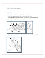
Step 2 – Radio unique Installation 

For assembling of radio interface; see radio unique installation instruction.  


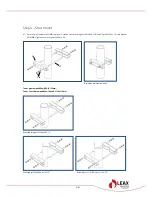
Step 3 – Antenna support 

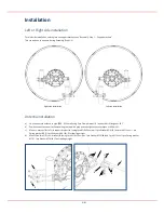
(Following steps/pictures describe a right side installation, see “Installation: Left or Right side installation” on page 6). 

 
a)


Mount 1pcs M8x16 screw ( 

5

 ) to Antenna support bracket ( 

1

 ). Tighten screw to torque of 17Nm ± 5%. 

b)


Mount Pivot bracket ( 

6

 ) to Antenna support bracket ( 

1

 ) using 1pcs M10x40 screw ( 

7

 ), 1pcs M10x35 screw ( 

8

 ) and 1pcs 

M10x30 screw ( 

9

 ). Fit screws finger tight. 

c)


Mount 2pcs M10 link screw ( 

10

 ) to Pivot bracket ( 

6

 ) using 1+1pcs M10x30 screw ( 

11

 ). Fit screws loosely. 

d)


Mount 4pcs M10x120 screw ( 

12

 ) to Pipe attachment bracket ( 

13

 ).  


e)


Mount Pipe attachment bracket ( 

13

 ) to Pivot bracket ( 

6

 ) using 1pcs M10x120 screw ( 

14

 ) and 1+2pcs M10 flange nut ( 

15

 ). Fit 

screw and nuts loosely. 


12 

13 

10 

11 

11 

13 

15 

15 

14 

Summary of Contents for 1.2m Antenna

Page 1: ...any liability for the results of improper or unsafe installation inspection maintenance or removal practices Torsgatan 5B Telephone 46 31 386 11 00 SE 411 04 G TEBORG customer lat leax com SWEDEN www...

Page 2: ...reflector edge without damaging the radome or reflector Included parts Item Qty Description A 1 Antenna B 1 Antenna support bracket 6 M10x35 screw with flange C 1 Antenna support Box 1 Pipe attachment...

Page 3: ...acket 1 using 5pcs M10x35 screw 2 Tighten screws to torque of 49Nm 5 b Mount Strut support bracket 3 using 3pcs M10x25 screws 3pcs Spring washer M10 3pcs Washers M10 4 Tighten screws to torque of 49Nm...

Page 4: ...hten screw to torque of 17Nm 5 b Mount Pivot bracket 6 to Antenna support bracket 1 using 1pcs M10x40 screw 7 1pcs M10x35 screw 8 and 1pcs M10x30 screw 9 Fit screws finger tight c Mount 2pcs M10 link...

Page 5: ...d 17 and 4 2pcs M10 nut 4 1pcs Washer M10 18 Tighten nuts to torque of 49Nm 5 Alternative bracket orientation Tower pipe compatibility 50 115mm Tower L section compatibility L40x40 L110x110mm Assembly...

Page 6: ...mm using 2pcs Clamp bracket 1 and 4pcs M10 flange nut 2 b Position the antenna so it will point along the radio link path and then tighten nuts to torque of 49Nm 5 c Mount L bracket 3 to Strut support...

Page 7: ...ent bracket 10 using 1pcs M8 U bolt 14 and 2 2pcs M8 nut 2 1pcs Washer M8 15 g Respect the maximum orientation angle indicated below This angle may be limited by the radio equipment h After completing...

Page 8: ...15 c On completion tighten screws to torque of 49Nm 5 Azimuth adjustment a Ensure 5pcs M10 nut 2 3 and 2pcs M10 screw 4 are slightly loose b Move 4pcs M10 nuts 2 along Azimuth screws to adjust direct...

Reviews: