background image

p20 

Mygo Seat -  Size 3 Stander User Manual 

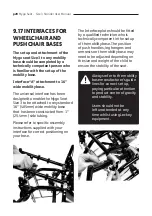
9.17 INTERFACES FOR 

WHEELCHAIR AND 

PUSHCHAIR BASES

The set up and attachment of the 

Mygo seat Size 3 to any mobility 

base should be completed by a 

technically competent person who 

is familiar with the set up of the 

mobility base.
Interface “A” attachment to 16” 

wide mobility base. 

The universal interface has been 

designed to enable the Mygo Seat 

Size 3 to be attached to any standard 

16” (405mm) wide mobility base 

that has been constructed from 1” 

(25.4mm) side tubing.

Please refer to specific assembly 

instructions supplied with your 

interface for correct positioning on 

your base. 

The Interface plate should be fitted 

by a qualified technician who is 

technically competent in the set up 

of the mobility base. The position 

of push handles, leg hangers and 

armrests on the mobility base may 

need to be adjusted depending on 

the size and weight of the child to 

ensure the stability of the seat.

Always refer to the mobility 

base manufacturer’s guide 

lines for correct set up, 

paying particular attention 

to product centre of gravity 

and stability. 

Users should not be 

left unattended at any 

time whilst using Leckey 

equipment.

Summary of Contents for Mygo Seat

Page 1: ...Mygo Seat Size 3 User Manual Supporting Children English...

Page 2: ...offer a high level of postural positioning while enabling function and mobility This manual shows how you can quickly easily and safely make use of all the functions The instructions on safety and ma...

Page 3: ...n p 7 08 Precautions and Contraindications p 9 09 How to unpack and assemble the seat p 10 10 Fitting the cushions p 21 11 Clinical setup for postural management p 26 12 Frequent adjustments for daily...

Page 4: ...tural support offered by Mygo Seat Size 3 is indicated for use for children with moderate to complex postural needs GMFCS IV V SECTION 02 CERTIFICATION Mygo Seat Size 3 is classified as a Class I Medi...

Page 5: ...Caution Finger Pinch Hazard Take care when assembling or adjusting the position of the seat components that your fingers do not get pinched when positioning seat components and tightening mountings C...

Page 6: ...e details of all setups reissue inspections and annual inspections of this product Caution Cleaning Power Washer Hose Do not use hoses or power washers on the frame components the electric seat lift s...

Page 7: ...any way Failure to follow instructions may put the user or carer at risk and will invalidate the warranty on the product 4 If in any doubt to the continued safe use of your Leckey product or if any p...

Page 8: ...s hotter than 40 C on the tray 15 Clean the product regularly Do not use abrasive cleaners Carry out maintenence checks on a regular basis to ensure your product is in good working condition 16 The pr...

Page 9: ...e the Mygo Seat Size 3 with one or more other Medical Device or other product Information on which combinations are possible can be found at leckey com All combinations listed have been validated to m...

Page 10: ...assemble the Mygo Seat Size 3 and attach it to its base The backrest will be folded down for shipping Raise it into the vertical position and while doing so slide the inner tube into the receiving out...

Page 11: ...calf supports Set to the desired position with the footplates facing forward and retighten the socket cap bolts with the multi tool Always make sure the foot plate is attached firmly Always make sure...

Page 12: ...s Pull the handle at the front of the seat unit up and then pivot the seat forward and down Once the front of the seat is lowered fully release the handle and push it forward to ensure it has fully en...

Page 13: ...re the slot in the reducing sleeve is aligned with the slot in the receiving bracket Set to the desired position and secure using the hand lever The Mygo Seat Size 3 has been designed to interface wit...

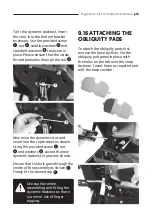
Page 14: ...together remove the plastic knob and washer Align the plastic angle adjuster mouldings and lateral bracket with the slot in the backrest and refit the washer and plastic knob 9 7 ATTACHING THE KNEEPAD...

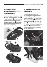
Page 15: ...rovided To remove or replace the attachment bolt reverse this process 9 9 ATTACHING THE SANDALS Place the sandal so that the attachment bolt goes through the slot in the footplate To secure on the und...

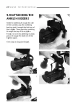
Page 16: ...e the webbing through the slot in the sandal Loop the webbing back up and through the bottom of the triglide Then pass the webbing through the top of the triglide Finally to lock the webbing in place...

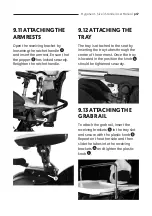
Page 17: ...TACHING THE TRAY The tray is attached to the seat by inserting the tray tubes through the centre of the armrest Once the tray is located in the position the knob should be tightened securely 9 13 ATTA...

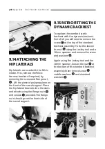
Page 18: ...uts and screws provided The flange nuts should go on the front side of the sacral support 9 15 RETROFITTING THE DYNAMIC BACKREST To replace the standard static backrest with the dynamic backrest first...

Page 19: ...shown Using the provided screw nut and washers secure the new dynamic backrest in place as shown Ensure that the bolt goes through the centre of the assembly as shown F Finally fit the domed cap E Use...

Page 20: ...from 1 25 4mm side tubing Please refer to specific assembly instructions supplied with your interface for correct positioning on your base The Interface plate should be fitted by a qualified technicia...

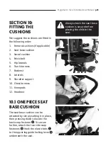
Page 21: ...Backrest 8 Laterals 9 Shoulder support 10 Chest harness 11 Kneepads 12 Headrest 10 1 ONE PIECE SEAT BASE CUSHION The seat base cushion can be attached by simply setting it in place then pressing down...

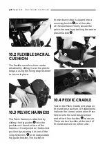
Page 22: ...o the desired position by securing it to one of the snap fasteners on the adjustable hip guide bracket The buckle on the tie down strap is clipped into a receiving buckle on either side of the seat ba...

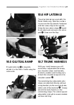
Page 23: ...required attach it to the Pelvic Cradle using the velcro side 10 7 TRUNK HARNESS With your trunk harness you will receive four adjustable side straps two shoulder straps and brackets the bolts washer...

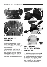
Page 24: ...and secure in place using the four snap fasteners in the backrest moulding Align the lower fasteners first and snap in place then secure the top fasteners 10 9 LATERAL SUPPORT PADDED CUSHIONS To atta...

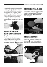
Page 25: ...th the padded side towards the inside of the seat Feed the plastic buckle through the slot in the cover then bring the two Velcro fastener straps around the bottom of the moulding and attach them to t...

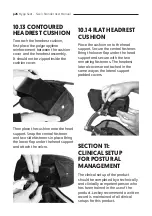
Page 26: ...ort and attach the velcro 10 14 FLAT HEADREST CUSHION Place the cushion on to the head support Secure the central fastener Bring the lower flap under the head support and secure with the two remaining...

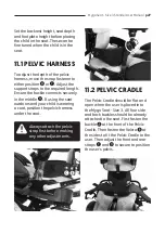
Page 27: ...he middle If using the seat outdoors and your child is wearing a coat position the pelvic harness under the coat B C Always attach the pelvic strap first before making any other adjustments 11 2 PELVI...

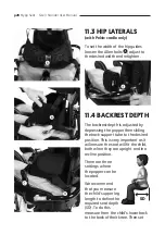
Page 28: ...child both when they are upright and in a recline position There are three settings where the popper can be located We recommend that you measure the child s upper leg length to define the required se...

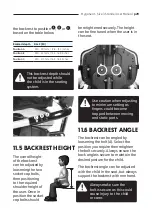
Page 29: ...then retighten the bolt securely Always ensure the back angle is secure to maintain the desired posture for the child The backrest angle can be adjusted with the child in the seat but always support...

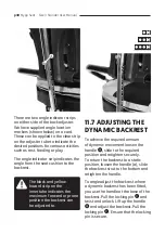
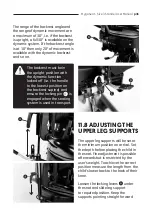
Page 30: ...ing or play The angle indicator strip indicates the angle from the seat cushion to the backrest 11 7 ADJUSTING THE DYNAMIC BACKREST To achieve the required amount of dynamic movement loosen the handle...

Page 31: ...levers under the seat and slide leg support to required position Keep the supports pointing straight forward The backrest must be in the upright position with the dynamic function locked off i e the h...

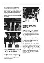
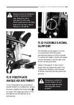
Page 32: ...footplate measure the distance from the back of the child s knee to the bottom of their heel You may have to adjust the angle to achieve the required foot position To adjust the angle loosen the bolt...

Page 33: ...vic positioning harness or Pelvic Cradle To adjust the height depth and angle loosen the bolts on either side with the multi tool provided Adjust the support to the correct angle then retighten the bo...

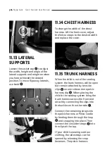
Page 34: ...the child is out of the seating system the trunk harness will be open but remain attached by two side clips on one side and one pelvic harness clip When placing the child in the seating system bring...

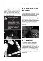
Page 35: ...1 16 ADJUSTING THE KNEEPADS The kneepads can be used as a limiter to help prevent the child from sliding forward in the seat It can also be used above the knee to prevent the child from raising their...

Page 36: ...als loosen screw move laterals to required angle and retighten 11 19 CONTOURED HEAD SUPPORT To adjust the height depth and angle of the contoured headrest loosen the hand knobs and when set to the des...

Page 37: ...t the height of the armrest loosen the hand knob set to the desired height and retighten To adjust the angle rotate ratchet handle until the desired position has been achieved Always use caution as fi...

Page 38: ...to suit the child s reach loosen knob adjust to the required depth and then re tighten Do not adjust the horizontal bars beyond the moulding except when you are removing the tray SECTION 12 FREQUENT...

Page 39: ...pelvic harness and Pelvic Cradle are fastened using the middle buckle and side velcro in the case of the Pelvic Cradle Always secure the pelvic harness or Pelvic Cradle first before fastening other bu...

Page 40: ...ten the centre buckle on the pelvic harness or Pelvic Cradle before making any other adjustments 12 3 CHASSIS The Mygo Seat Size 3 is designed to fit onto a range of chassis This user manual shows the...

Page 41: ...t and attach the lead A to the battery and switch on the mains supply power When charged switch off mains power remove the adaptor plug and disconnect the lead from the battery The battery charge shou...

Page 42: ...ys use caution as hands could become trapped when height adjusting the base 12 6 TILT IN SPACE The tilt in space can be angled while the user is in the seat Before you adjust the tilt in space angle o...

Page 43: ...unit to jolt and possibly cause injury to the child Please use handle bars when operating tilt in space Always check with your therapist that the use of tilt in space will not cause any obstructions t...

Page 44: ...hest harness Check the harness and laterals are secure to ensure the child is safe and cannot slide forward in the seat as this may restrict their breathing 12 9 SANDALS To position the user s feet in...

Page 45: ...set to the desired height and retighten To adjust the angle rotate hand knob until the desired position has been achieved To remove the armrest completely for side transfer or assist in getting the c...

Page 46: ...To set the depth of the grab rail to suit the child s reach loosen knob adjust to the required depth and then re tighten Do not adjust the horizontal bars beyond the mouldings except when you are remo...

Page 47: ...and the range of dynamic movement are a maximum of 30o i e if the backrest is upright a full 30o is available on the dynamic system If the backrest angle is at 10o then only 20 of movement is availabl...

Page 48: ...When cleaning we recommend that you use only warm water and a non abrasive detergent 3 Staining should be removed as quickly as possible with absorbent cloth towels or a sponge Routine soap and warm...

Page 49: ...3 Check all castors are moving freely and lock securely 4 Ensure the handle and locking pin on the seat interface plate is fully engaged and the seat unit is securely fixed onto the chassis 5 Ensure t...

Page 50: ...rely to prevent accidental height adjustment of the chassis 4 Adjust the seat to its maximum range of tilt in space and ensure that the locking lever locks the seat out securely at varying point in th...

Page 51: ...end the use of an automated fogger disinfection system that is used to completely cover the product surfaces with a disinfectant agent The manufacturer s instructions for the chosen system should be r...

Page 52: ...y be carried out by technically competent persons who have been trained in the use of the product All international service enquiries should be directed to the appropriate Leckey distributor who will...

Page 53: ...lift 102 2766 Indoor Hi Low with hydraulic manual lift 102 2754 Hi Low Chassis Powered Complete 102 2753 Hi Low Chassis Foot pedal Complete Accessories 117 802 Pelvic Harness Brackets Medium 133 731 P...

Page 54: ...470mm 18 5 Top of Seat to Floor min max 360mm 14 2 700mm 27 5 Armrest Height 210mm 8 3 260mm 10 2 Tray Size 550 x 480mm 21 6 x 18 9 LECKEY HI LOW BASE OPTIONS 6 3 LINAK Actuator specification 281209...

Page 55: ...Powered Top of Seat to Floor Min 370cm 15 inches Max 675cm 27 inches Tilt in Space Prone Recline 10 25 137 600 Base Weight 12kg 26 5lbs Charging current Max 500mA Green LED for power on Yellow LED fo...

Page 56: ...Instructions for Use CE mark Warning Do not dispose in domestic waste Manufacturer Model Number Serial Number Max Occupancy Weight Date of Manufacturer Latex Free Unique Device Identification Crash T...

Page 57: ...Mygo Seat Size 3 Stander User Manual p57 NOTES...

Page 58: ...Canadian Distributor Sunrise Medical 237 Romina Drive Unit 3 Concord ON L4K 4V3 T 1 800 263 3390 F 1 800 561 5834 E mkt canada sunmed com sunrisemedical ca James Leckey Design Limited 19 Ballinderry...

Reviews: