background image

Mygo Max User Manual  

p29

SECTION 12: 

FREQUENT ADJUSTMENT 

FOR DAILY USE

(Therapists/carers/parents)


Parents and carers should be shown 

how to make frequent adjustments 

and be made aware of the safety 

checks in Section 7 by a technically and 

clinically competent person who has 

been trained in the use of the product. 

Leckey recommend that a written record 

is maintained of all parent and carers 

who have been trained in the use of this 

product.

Before transferring the child into the seat 

carry out the daily product inspection 

as outlined in section 14 of this user 

manual. Adjust the seat to a comfortable 

height to facilitate transfer. Lock all the 

castors, ensuring that they are facing 

outwards to maximise product stability. 

Make sure the safety buckle on the chest 

harness is released and is out of the way 

to facilitate transfer.

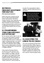
If the seat has flip-away thoracic 

laterals, first move these out of the 

way using knob a. Unclip the Leeway 

Pelvic Cradle in the middle, undo the 

side velcro of the Leeway Pelvic Cradle 

and allow the harness to open out to 

facilitate transfer. Lastly if sandals are 

fitted open the straps. You are now 

ready to transfer or hoist the child into 

12.1 TRANSFERRING 

YOUR CHILD INTO AND 

OUT OF THE SEAT

Always secure the Leeway 

Pelvic Cradle first before 

fastening other buckles or 

harnesses. Adjust the harness 

so the child cannot slide or 

creep forward in the seat.

the seat. The Leeway Pelvic Cradle is 

fastened using the middle buckle, and 

side velcro.

The correct positioning and tensioning 

of the Leeway Pelvic Cradle is key to a 

child’s postural management, affecting 

their comfort and ability to carry out 

activities. Please consult with your 

therapist to ensure the Leeway Pelvic 

Cradle is positioned correctly and that 

the straps are tensioned appropriately.

12.2 ADJUSTING THE

LEEWAY PELVIC CRADLE

Summary of Contents for Mygo

Page 1: ...Mygo Max User Manual Supporting Children English...

Page 2: ...level of postural positioning while enabling function and mobility This manual shows how you can quickly easily and safely make use of all of the functions The instructions on safety and maintenance...

Page 3: ...aining Record 07 Safety Information 08 Precautions and Contraindications 09 How to Unpack and Assemble 10 Fitting the Covers 11 Clinical Setup for Postural Management 12 Frequent Adjustments for Daily...

Page 4: ...ns As the manufacturer James Leckey Design Limited declares that this product conforms to the Medical Device Regulation 2017 745 UK Medical Device Regulations 2002 Medial Device Directive 93 42 EEC an...

Page 5: ...seat 7 Caution Cleaning Clean the seat regularly to prevent the build up of dirt on the seating elements and the chassis Accumulated dirt can prematurely wear the seat cushions and encourage corrosio...

Page 6: ...of this product SECTION 06 PRODUCT TRAINING RECORD PARENTS TEACHERS CARERS SECTION 04 TERMS OF WARRANTY The warranty applies only when the product is used according to the specified conditions and fo...

Page 7: ...e product is stationary ensure that all castors are locked and facing away from the base as this will improve product stability This is especially important when the tilt in space or back recline faci...

Page 8: ...tremes of temperature The safe operating temperature range of the product is 5 to 40 deg Celsius 18 Always check the plastic hand knobs on the push handle are tightened securely before you move the se...

Page 9: ...ty Children dependent on the use of percutaneous endoscopic gastrostomy Medical instability including compromised respiratory or cardiovascular function Dependant on 3rd party life sustaining apparatu...

Page 10: ...YSTEM Check parts Congratulations on purchasing your Mygo Max All of the parts will be contained in polythene bags with each one clearly labelled Carefully remove them from the boxes and check all the...

Page 11: ...f the seat To do this pull the pin out and rotate through 90 degrees Carefully lift the seat and place it into the chassis At the rear of the underside of the seat you will see a receiving channel Pla...

Page 12: ...n so it engages in front of the handle If it hits the handle then the seat is not inserted properly Remove and repeat process outlined above 9 3 ATTACHING THE PUSH HANDLE Always check the handle and l...

Page 13: ...and washer Align the plastic angle adjuster mouldings and lateral bracket with the slot in the backrest and refit the washer and plastic screw 9 4 ATTACHING THE HEADREST 9 5 ATTACHING THE LATERAL SUPP...

Page 14: ...centre of each armrest Once the tray is located in the position the knob A should be tightened securely 9 8 ATTACHING THE ARMRESTS 9 9 ATTACHING THE TRAY If sandals are required they can be attached t...

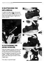
Page 15: ...en the screw to secure 9 10 ATTACHING THE HIP LATERALS Slide the webbing through the slot in the sandal Loop the webbing back up and through the bottom of the triglide Then pass the webbing through th...

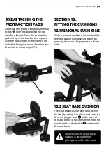
Page 16: ...CTION PADS SECTION 10 FITTING THE CUSHIONS Slide a femoral cushion onto each of the femoral supports and secure them by pressing down on the poppers on either side The seat base cushion can be attache...

Page 17: ...de the flaps over the top of the backrest and underneath the bottom of the backrest and secure with the snap fasteners 10 3 BACKREST CUSHION Fasten the Leeway Pelvic Cradle and place on the seat base...

Page 18: ...the top Slide the cushion covers over the hip lateral with the open zip on the outside Close the zip and secure the Velcro flap 10 5 SACRAL CUSHION 10 6 HIP LATERALS Slide each of the four straps B th...

Page 19: ...ure the Velcro flap 10 8 LATERAL SUPPORTS The chest harness can be attached by clipping the male buckle A into the female buckle B at either side of the lateral supports 10 9 CHEST HARNESS Place the c...

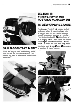
Page 20: ...AGEMENT The Leeway Pelvic Cradle should be flat and open when the user is placed into the Mygo Max All four side and starps should be already attached to the seat First fasten the buckle A at the fron...

Page 21: ...so be angled to help support abduction adduction or windsweeping 11 2HIPLATERAL To adjust the angle of the hip laterals loosen the screw B on the hinge of the hip lateral Adjust to the required angle...

Page 22: ...ight forward at this time unless wind sweeping or adduction abduction must be accommodated in which case set the angle accordingly using the knobs again To change the angle loosen the screw at the bot...

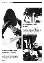
Page 23: ...screws There are two screws per femoral guide 11 6 ADJUSTING THE FEMORAL GUIDES To raise or lower the height of the footsupport loosen screw A adjust to the required position and retighten the screw s...

Page 24: ...t the calf support angle loosen the screw B at the top of the calf support move front or back to the required angle then retighten the screw To position the sandals simply loosen the knob A under the...

Page 25: ...side of the bracket move to the required position and retighten the screws To adjust the angle loosen both the screws B on the ball and socket joint Position the support at the required angle and ret...

Page 26: ...ion The complex laterals can also be angled to allow the pad to contour to the user s shape To adjust loosen the bolt A at the centre of the pad angle the pad to the required position and retighten th...

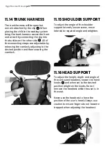
Page 27: ...en securing the camlock 11 14 TRUNK HARNESS To adjust the angle of the shoulder support laterals loosen screw move laterals to required angle and retighten 11 15 SHOULDER SUPPORT To adjust the height...

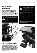
Page 28: ...obs A under the armrest set to the desired position and re tighten securely 11 17 ARMREST ADJUSTMENT 11 18 TRAY ADJUSTMENT Always use caution as fingers could become trapped in the slot when adjusting...

Page 29: ...cilitate transfer If the seat has flip away thoracic laterals first move these out of the way using knob a Unclip the Leeway Pelvic Cradle in the middle undo the side velcro of the Leeway Pelvic Cradl...

Page 30: ...he velcro tabs D If using the seat outdoors and your child is wearing a coat position the Leeway Pelvic Cradle under the coat The powered chassis can be easily adjusted with the push button control ha...

Page 31: ...n inserting the battery into the charger the green diode starts flashing with an interval of 1 sec during the charging process When charging is finishing the green diode stops flashing and turns on co...

Page 32: ...and side of the pedal To unlock pull the pin out and rotate 90 degrees the pedal can then be operated The locking pin C should be kept in the locked position when you are not adjusting the chassis 12...

Page 33: ...apist that the use of tilt in space will not cause any obstructions If the child requires chest support as part of their postural support programme the seat will be fitted with rigid laterals or a com...

Page 34: ...SANDALS If the child is wearing sandals or light footwear check the straps to make sure the webbing does not irritate the skin 12 10 TRAY ADJUSTMENT The activity tray can be used for a range of functi...

Page 35: ...CARE INFORMATION How to Maintain When cleaning the product we recommend that you use only warm water and a nonabrasive detergent Never use organic solvents or dry cleaning fluids Upholstery and fabri...

Page 36: ...use THERAPISTS PARENTS CARERS If in any doubt to the continued safe use of your Leckey product or if any parts should fail please cease using the product and contact our customer service department or...

Page 37: ...ts Leeway Pelvic Cradle hip guide attachment bolts Footrest height and angle adjustment 3 Check the chassis height adjustment mechanism is working properly If the chassis is foot pedal operated ensure...

Page 38: ...st to remove accumulated soiling prior to disinfecting sanitising 1 Where possible we recommend the use of an automated fogger disinfection system that is used to completely cover the product surfaces...

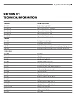
Page 39: ...Low base Hydraulic 33 760 KIT MYMX Indoor Outdoor Hi Low base Powered Accessories 161 688 Armrests 152 3600 Sandals 161 610 Lower Leg Supports 161 689 Flipaway lateral supports 161 690 Complex lateral...

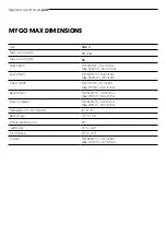
Page 40: ...3 8 inches Max 500mm 120 inches Chest Width Min 170mm 6 7 inches Max 270mm 10 6 inches Back Height Min 330mm 13 2 inches Max 510mm 20 4 inches Seat to Sandal Min 330mm 13 2 inches Max 510mm 20 4 inche...

Page 41: ...nual p41 Table of Symbols Symbol Meaning Medical Device Read the Instructions for Use CE mark Warning Do not dispose in domestic waste Manufacturer Product code Serial number Max occupancy weight Date...

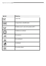
Page 42: ...Mygo Max User Manual p42 Symbol Meaning Latex free Unique Device Identification Machine wash water temperature 40 C Tumble dry low heat Do not iron Do not bleach Handwash Do not dry clean...

Page 43: ...Mygo Max User Manual p43 NOTES...

Page 44: ...anadian Distributor Sunrise Medical 237 Romina Drive Unit 3 Concord ON L4K 4V3 T 1 800 263 3390 F 1 800 561 5834 E mkt canada sunmed com sunrisemedical ca James Leckey Design Limited 19 Ballinderry Ro...

Reviews: