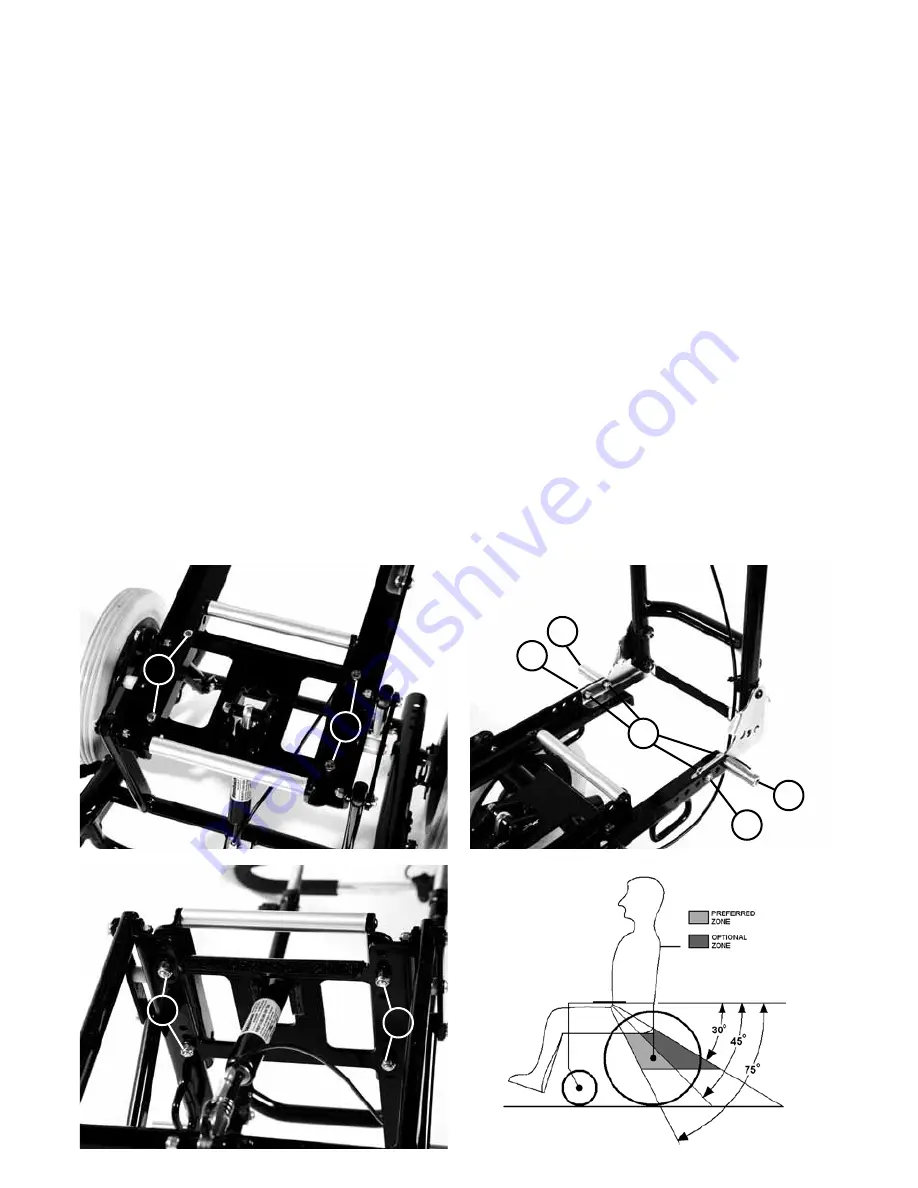
7.2 Handle bar depth
The mobility base will arrive with the handle bar
fitted in a position likely to be suitable for the
seating system to be attached to it. In order to
adjust the position of the handle bar, please
refer to Fig 2.
Remove the 2 screws (A), 2 lap belt posts (B)
and nuts (C) retaining the handle bar assembly
and slide it forward or backwards as desired.
Refit the attachment screws, posts and nuts.
Ensure all nuts & screws are re-tightened to
ensure the handle bars are firmly attached to
the base.
The lap belt posts and screws can be fitted
in either the forward or rearward position,
ensuring the angle of the lap belt is correct (Fig
3) and it does not interfere with any parts of the
base throughout its range of tilt.
7.1 Seating Interface
The mobility base will arrive with the interface
fitted in a position likely to be suitable for the
seating system to be attached to it. There are
five mounting positions to choose from. The
foremost three positions are suitable for the
Keat Seat and the rearmost are suitable for
the Mygo Seat. In order to adjust the position
of the interface, please refer to Fig 1a and 1b.
Remove the 4 screws (A) and nuts (B)
retaining the interface and slide the interface
forward or backwards as desired. Refit the 4
screws and nuts. Ensure all screws & nuts are
re-tightened to ensure the seating system will
be firmly attached to the base when fitted.
A
B
C
B
A
Fig 2
Fig 3
Fig 1a
Fig 1b
A
B
B
A
Summary of Contents for Tour Mobility Base
Page 1: ...Leckey Tour Mobility Base User Instructions...
Page 2: ......
Page 10: ...Adjusting the mobility base 8...
Page 15: ...Accessories 9...
Page 20: ...Maintenance cleaning and care 10...
Page 31: ......


