Control Panel
Using the supplied anchors and screws, the Control Panel should be mounted on a flat, sturdy,
vertical sur face away from direct exposure to sunlight. The Control Panel is equipped with a 3.65m
DC cell cord and flow detector cord. For ease of installation, please ensure that both cords connect
to the cell and flow detector while still providing slack in each cord for future service. Using a
torpedo level and permanent marker, hold and level the Control Panel on the surface to be mounted
and dot each of the (4) mounting holes. Using a .63 cm drill bit, drill to a depth of 2.5 cm and install
the supplied anchors. The Control Panel is now ready to receive the (4) mounting screws to secure
the installation.
DO NOT SHOOT OR PERMANENTLY ATTACH THE CONTROL PANEL TO THE WALL! This will void the
WARRANTY.
CAUTION - YOU MUST REMOVE THE OUTPUT CONTROL DIAL BEFORE ATTEMPTING TO REMOVE
THE COVER. FIRST PRY OFF THE CAP AT THE TOP OF THE KNOB, WHICH WILL REVEAL THE HEX
NUT. LOOSEN THE NUT AND LIFT OFF THE KNOB.
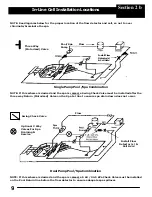
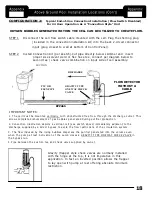
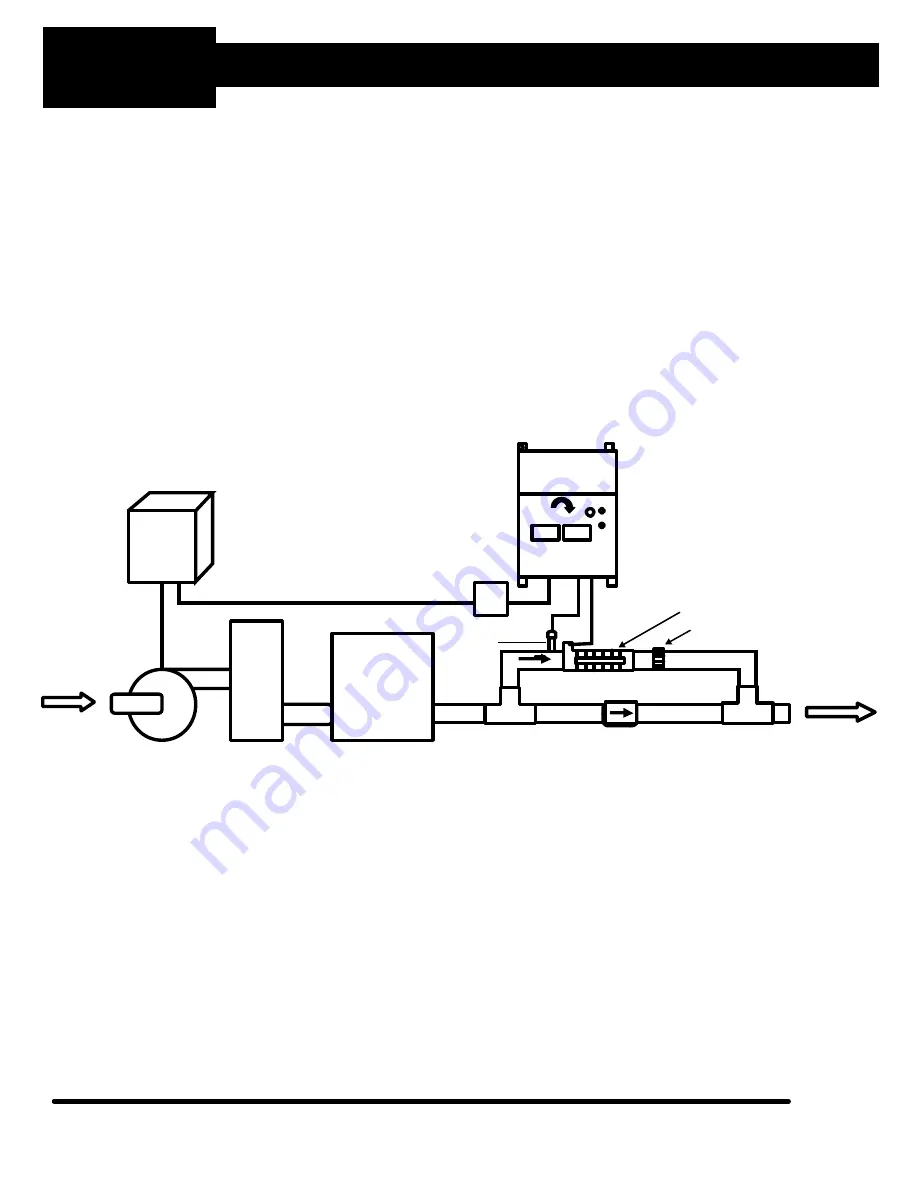
Typical In-Line Equipment Power
Connection (220V)
NOTE 1 : FOR 24 HOUR OPERATION AS A "CONVECTION STYLE" INSTALLATION, SEE APPENDIX
(PAGE 18)
NOTE 2: IF YOU NEED A TIME CLOCK FOR CONTROL OF THIS UNIT AND YOUR 110 VOLT POOL
PUMP (PLUG IN), ASK ABOUT OUR PORTABLE TIME CLOCK .
Control Panel & Cell Installation
Section 2 b
8
LIBERTO
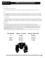
Output Control
Required Salt Level
2500 - 3500
Flashing Green Light –
Generating Purifier
Flashing Red Light
– Check System
External
Filter
Pump
Control
System
LOADSIDE AC POWER
FROM EXTERNAL
FILTER PUMP
CONTROL SYSTEM
TO
POOL
PUMP
F
I
L
T
E
R
HEATER
¶ 
¶ 
SINGLE GANG
JUNCTION
BOX (WIRENUT
CONNECTIONS)
POWER SUPPLY
FLOW DETECTOR
DC CELL CORD
CELL
CELL UNION (TYP.)
FROM
POOL
OPTIONAL 2 LB / 13.8 kPa CHECK VALVE (FOR HIGH
FLOW CONDITIONS OVER 50 GPM / 11.3 M3 / HR.
Summary of Contents for 27315
Page 19: ......


