22
3.0 Power Supply,
continued
745-573-B0-001 REV. A
D
E
G
F
B
A
C
NOTE:
The CPR module weighs 56 lbs/25 kg. (65 lbs./30 kg for the 24 amp model), and the
center of gravity is offset to the right. The unit may be lifted using both of the lifting
handles on the front of the module.
CAUTION
: When pulling the unit forward from a shelf, be sure to support the right hand
rear corner.
INSTALLATION
PROCEDURE
1.
Verify the battery breaker on the front panel of the CPR
TM
is open (off).
2.
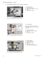
Connect the green and yellow output harness on the CPR
TM
UPS to the mating connector on the
harness that is installed in the cabinet. Verify the connector colors match.
(Green is electrically tied to chassis ground-electrically the same as white in Alpha enclosures)
3.
Connect the green ground wire from the CPR
TM
UPS to the back of the mounting bolt that holds
the exterior ground clamp to the wall of the enclosure. Use the #10 hardware provided.
4.
For those power supplies with IEC power cords, plug the cord into the receptacle on the left side of
the power supply. Use only an HAR-approved power cord for 50 Hz installations. Tighten the
screw on the clamp until the power cord is secure (if clamp is installed).
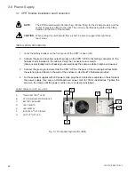
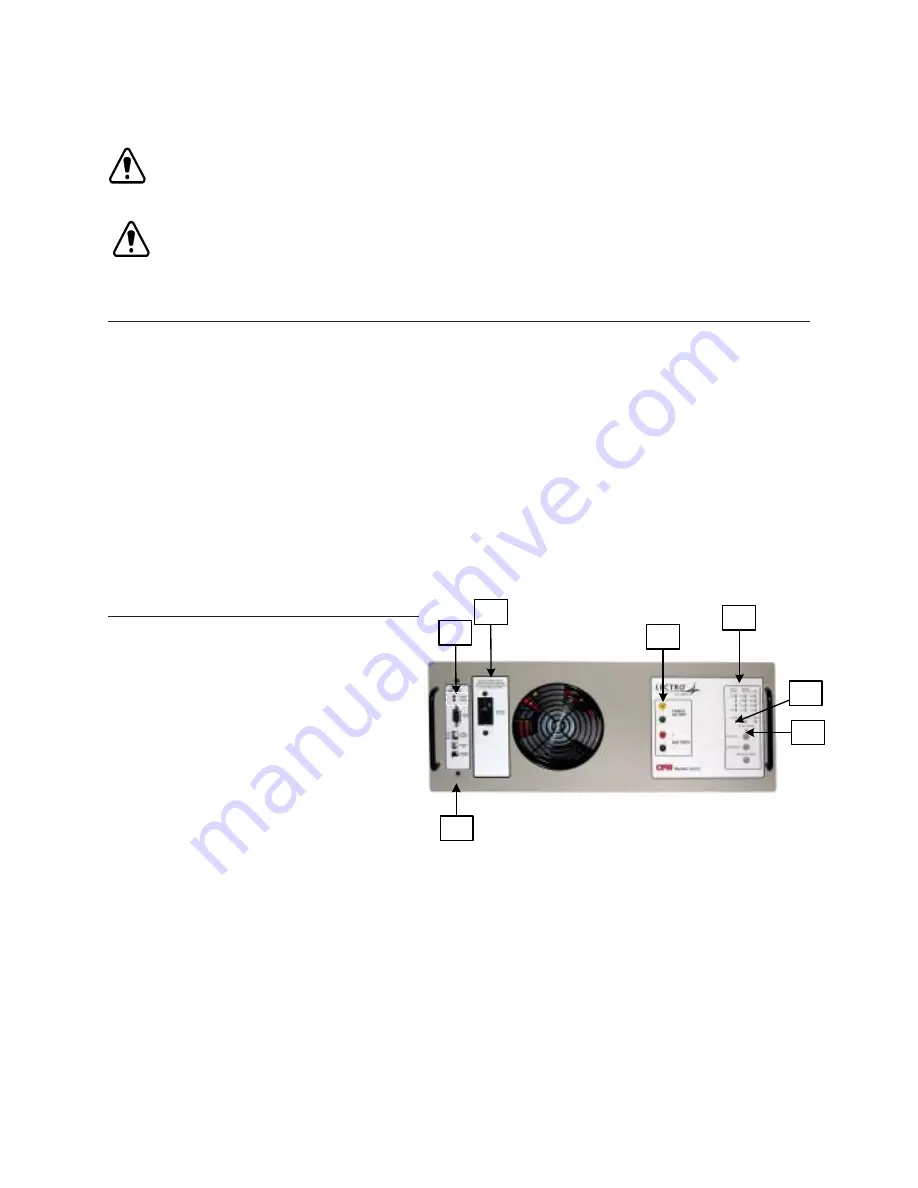
FRONT
PANEL
LAYOUT
,
ALL
UNITS
A
.
"
WEAK
BATTERY
"
LEDS
B
.
CPR
COMMUNICATOR
MODULE
C
.
BATTERY
BREAKER
D
.
TEST
POINTS
E
.
LED
DISPLAY
F
.
INVERTER
"
ON
"
DISPLAY
G
.
OUTPUT
"
ON
"
LED
Fig. 3-1 Front panel layout (all models)
3.1 CPR
TM
Module Installation and Connection


