29
3.0 Power Supply
,
continued
745-573-B0-001 REV. A
3.2
Battery Installation and Connection,
continued
3.2.4
Connecting an Additional 36V Battery String
NOTE:
This procedure assumes that the additional battery string is being installed in a
Lectro brand cabinet.
1.
Confirm the CPR
TM
DC circuit breaker is off (down).
2.
Place the batteries in the bottom of the cabinet with the negative terminals (-) at the rear of the
cabinet.
3.
Connect the red battery lead from the lower shelf at the positive (+) terminal of the left battery.
Torque connection to 60 inch-pounds (6.8 Newton-meters).
4.
Disconnect the red battery lead cable from the upper shelf at the positive (+) terminal of the left
battery. Reconnect this lead with the red lead of the inter-shelf connection cable.
5.
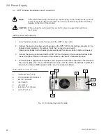
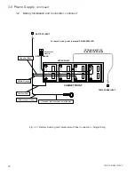
Connect the two (2) battery interconnection jumpers as shown below. Torque all connections to
60 inch-pounds (6.8 Newton-meters).
6.
Disconnect the black battery lead cable from the upper shelf at the negative (-) terminal of the
right battery. Reconnect this lead with the black lead of the inter-shelf connection cable. Torque
connection to 60 inch-pounds (6.8 Newton-meters).
7.
Measure the DC voltage to ensure proper installation of all battery wiring. Open circuit DC voltage
should measure at least 36 volts across both parallel strings.
8.
Verify the red and black Anderson connector pair is properly attached to the left side of the CPR
module.
+
-
+
-
+
-
+
-
+
-
+
-
UPPER
SHELF
LOWER
SHELF
CABINET FRONT
RED
BLACK
Fuse
Fuse
Red and Black
Anderson Connector
Fig. 3-8, 36V Battery Connections – parallel strings P/N 870-132-23


