30
3.0 Power Supply,
continued
745-573-B0-001 REV. A
3.2
Battery Installation and Connection,
continued
+
-
+
-
+
-
+
-
-
+
-
-
+
UPPER SHELF
LOWER SHELF
CABINET FRONT
RED
BLACK
OPTIONAL XM STYLE
TEMPERATURE PROBE
-
Negative (Black)
Middle (Orange)
Positive (Red)
Middle, Longer
lead (Orange)
BATTERY SENSE INPUT
TEMP PROBE INPUT
+
+
Gray Anderson
Connector
For Level 3 wiring, refer to manual P/N 040-0080-1501
3.2.5
Battery Removal
1.
Turn the DC circuit breaker off (down) and observe all precautions for the safe handling
of batteries as previously outlined.
2.
Remove all batteries in the reverse order of installation.
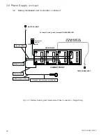
Fig. 3-9, 48V Battery Sensing and Temperature Probe Connection – Parallel Strings

