41
5.0 Status Monitor
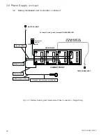
, Continued
745-573-B0-001 REV. A
The operation of the status monitor is automatic and carries out its functions without the direct intervention
of the operator. The purpose of the status monitor is to indicate the operating conditions of the CPR power
supply. There are three levels of status monitoring:
LEVEL ONE
Indicates locally (at the power supply) only. This can be a combination of the
external cabinet LED indicators and/or the LED’s on the CPR power supply.
This level is NOT compatible with transponder devices. The information
available in addition to the information displayed on the front of the CPR
power supply is as follows:
•
Weak battery string indicators (located on the Communicator module).
•
Normal operation, Standby operation and Alarm condition (with the
external cabinet LEDs) The weak battery indicators can be reset by
pushing the Battery LED Reset button, located on the front of the CPR
power supply.
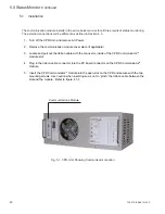
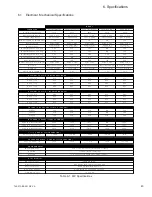
Level One Commmunicator Module features:
1.
Weak Battery Indicator LEDs (one per string).
2.
Battery Sensing Harness (connects to battery terminals).
3.
Wiring to external cabinet LEDs.
LEVEL TWO
Allows for remote status monitoring with access to additional, more detailed
information. Level Two is essentially the same as Level One with the addition
of a DE-9 connector located on the front of the communication module. The
DE-9 connector is used to indicate remotely via a third party transponder
device. The data available is in RS-232 format. The popular “
Palm Pilot”
PDA
device may also be connected to this port using a Palm Pilot application and
instructions available from Lectro. A telephony modem may also be connected
to the RS-232 port. Be sure to disable “hardware handshaking” for proper
operation of the modem in this application.
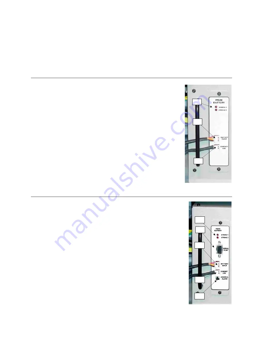
Level Two Commmunicator Module features:
1.
Weak Battery Indicator LEDs (one per string).
2.
RS-232 DB-9 port for connection between Transponder, Modem, Laptop
PC, or customer-supplied PDA.
3.
Battery Sensing Harness (connects to battery terminals).
4.
Wiring to external cabinet LEDs.
5.
Door Tamper switch connector (shown with shorting jumper).
1
2
3
1
2
3
4
5
5.2
Operation


