5
Preface
745-573-B0-001 REV. A
Figures & Tables
1.0 Overview
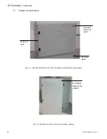
Fig. 1-1,
Ground Mount (Front View of 4 battery cabinet with ground skirt) ................ 14
Fig. 1-2,
Pole Mount (Front View of 8 battery cabinet) ................................................ 14
Fig. 1-3,
Pole Mount (Rear View of cabinet) ............................................................... 15
Fig. 1-4,
Typical Placement of Disconnect Breaker on rear of Cabinet ....................... 15
Fig. 1-5,
Coax “Feed Thru” Adapter Normal Location (Bottom Shelf) ......................... 15
2.0 Cabinet Installation
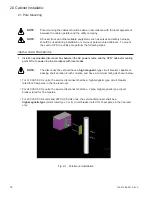
Fig. 2-1,
Pole Mount Installation .................................................................................. 16
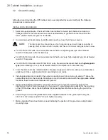
Fig. 2-2,
Pad Dimensions ............................................................................................ 19
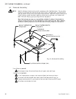
Fig. 2-3,
Enclosure Grounding .................................................................................... 20
3.0 Power Supply
Fig. 3-1,
Front panel layout (all models) ...................................................................... 22
Fig. 3-2,
Connection points for 60Hz, 15A units .......................................................... 24
Fig. 3-3,
Connection points for 50Hz units .................................................................. 24
Fig. 3-4,
Connection points for 60Hz, 24A units .......................................................... 24
Fig. 3-5,
48V Battery Connections – Single String ...................................................... 26
Fig. 3-6,
36V Battery Connections – Single String ...................................................... 27
Fig. 3-7,
48V Battery Connections – Parallel Strings .................................................. 28
Fig. 3-8,
36V Battery Connections – Parallel Strings .................................................. 29
Fig. 3-9,
48V Parallel Battery Sense Wiring ................................................................ 30
Fig. 3-10,
36V Parallel Battery Sense Wiring ................................................................ 31
Fig. 3-11,
36V Single Battery Sense Wiring .................................................................. 32
Fig. 3-12,
Front Panel Display ...................................................................................... 33
Fig. 3-13,
Maintenance Log Sheet ................................................................................ 36
4.0 Troubleshooting
Table 4-1, Troubleshooting guide, Part 1 ....................................................................... 38
Table 4-2, Troubleshooting guide, Part 2 ....................................................................... 39
5.0 Status Monitoring
Fig. 5-1,
CPRBattery Removal
6.0 Specifications
Table 6-1, Specifications ................................................................................................ 43
Table 6-2, Specifications ................................................................................................ 44


