background image

Performer 

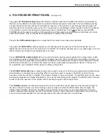
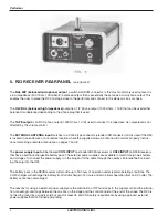
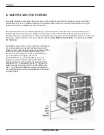
5.  R33 RECEIVER REAR PANEL  

(see figure 4) 

The 

BAL MIC (balanced microphone) output

, a switchcraft D3M connector, is the most commonly used output. It is 

a low impedance (200 ohms, 100 millivolt), balanced output that is essentially the same as a microphone output. This 
enables the user to place the R33 on stage close to the performer and connect to the stage mic box or snake. 

The 

HI-Z BAL (balanced high impedance)

 output is a 1/4” phone output (1000 Ohms, 1 Volt) that can be used either 

balanced or unbalanced depending on the phone plug that is used. 

The 

TAPE output

 is an RCA phono output (1500 Ohms, 1 Volt) used to connect to a tape deck. Its output level is not 

affected by the volume control. 

The 

EXTERNAL ANTENNA input

 matches to a PL259 type connector (standard CB connector) and is used if the R33 

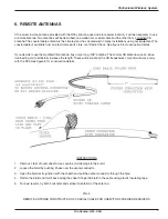
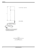
is located in an enclosure or at a remote location where the supplied screw-in antenna will not work properly. Instruc­
tions for making a remote antenna are on pages 7 and 8. 

The 

power supply input

 will be labeled 

CH12 INPUT

 on standard R33A receivers or 

CH40 INPUT

 on R33B receivers 

that have a built in rechargeable battery pack. The external power supplies are available to match foreign wall outlets 
and voltages. To connect the power supply, run the plug end of the cable through the nearby strain relief before insert­
ing the plug into the R33. 

The battery pack in the R33B receiver will provide up to 16 hours of operation under typical operating conditions. The 
CH40 charger will recharge the battery from full discharge in 14 hours and also allows operation from an AC outlet. The 
battery cannot be overcharged. 

The reasons for using an external power supply are the elimination of RF hum loops in the supply cord and the elimina­
tion of audio ground loops between the mic box on the stage and the control board at the end of the snake. The R33 is 
not tied to ground by a supply cord but can still meet UL and CSA safety requirements by using approved, external 
power supplies that don’t require grounding. 

LECTROSONICS, INC. 

Summary of Contents for Freedomike Performer

Page 1: ......

Page 2: ...Performer LECTROSONICS INC 2 ...

Page 3: ...IONS REGULATIONS 2 M33 TRANSMITTER 3 R33 RECEIVER FRONT PANEL 5 R33 RECEIVER REAR PANEL 6 REMOTE ANTENNAS 7 SYSTEM SETUP AND OPERATION 9 MULTIPLE CHANNEL SYSTEMS 10 TROUBLE SHOOTING 11 SERVICE AND REPAIR 14 RETURNING UNITS FOR REPAIR 14 ACCESSORIES Table B Rio Rancho NM USA 3 ...

Page 4: ... range It is available on 5 different frequen cies The M33 transmitter and the R33 receiver must be on the same frequency The frequency of operation is marked on the serial plate In addition the serial plate color is different for each frequency We have not found that any of the 5 frequencies have any advantages or disadvantages over the others If more than one system is being used simulta neously...

Page 5: ...o blink After the indicator begins blinking you will have about 4 hours of use remaining When the battery gets very low the indicator will glow solidly indicating 1 hour or less remaining When the transmitter is first turned on it may require several minutes to get a true battery reading For example if a dead battery were not used for a day or so and then was used in the M33 it might indicate for ...

Page 6: ... We have provided a spare set screw and allen wrench in case you have misplaced the one that came with your mic You may also drill and tap a 4 40 hole in other micro phones to use the set screw See figure 2 below If you don t use the set screw the wavy rubber ring that is provided can be used to remove most of the play between the M33 transmitter and your microphone LECTROSONICS INC 6 ...

Page 7: ...his indicator is similar to the distortion or clipping indicator used on some control boards and amplifiers However on this system there is considerably more headroom 16dB due to the compandor circuitry and soft compressor circuitry built into the transmitter It is normal for this indicator to flash occasionally during operation Section 7 will cover in more detail the use of the MOD LEVEL lights i...

Page 8: ...truc tions for making a remote antenna are on pages 7 and 8 The power supply input will be labeled CH12 INPUT on standard R33A receivers or CH40 INPUT on R33B receivers that have a built in rechargeable battery pack The external power supplies are available to match foreign wall outlets and voltages To connect the power supply run the plug end of the cable through the nearby strain relief before i...

Page 9: ...long 108 antenna The shorter CB antennas use an induc tive loading coil to artificially increase the length These will resonate at the CB frequencies only and will work poorly with the R33 See figure 6 for construction details INSTRUCTIONS 1 Remove 7 feet of outer sheath Use care to avoid damage to the braid 2 Loosen the braid by pushing it back over the center conductor 3 Open the braid at its ju...

Page 10: ...ormer CUT OFF THIS 2 SECTION BASE SPRING AMPHENOL 83 1SP PLUG or equivalent TO REMOTE ANTENNA CONNECTOR ON R33 SERIES RECEIVER FIG 6 CB ANTENNA MODIFIED FOR USE WITH R33 SERIES RECEIVERS LECTROSONICS INC 10 ...

Page 11: ...D LEVEL lamp indicates the transmitter gain is low Turn the transmitter gain control gently clockwise until the red LED blinks on the loudest audio peaks 2 A red MOD LEVEL lamp that is lit at medium audio levels or very frequently indicates that the transmitter gain is too high The gain should be reduced by turning the gain control on the M33 transmitter gently counterclock wise Excessive gain may...

Page 12: ...e same frequency at the same location creates an identical problem Each M33 transmitter that is on must have a differ ent frequency Each M33 receiver can be hooked up with its own antenna or can be stacked using the remote antenna connector Figure 7 shows three receivers using one antenna with the remote antenna jacks coupled together using short stacking banana plug cords These are available from...

Page 13: ...ls and singer is having difficulty hearing monitors during loud portion of vocals POSSIBLE CAUSE 1 OFF MUTE ON switch in off position Batteries low in R33B rechargeable version 2 Power supply not plugged in or AC receptacle dead 3 Power supply cable or power supply defective 1 M33 not turned on 2 Dead battery in M33 3 M33 is on different frequency than R33 4 Antenna not hooked up to R33 properly 5...

Page 14: ...rechargeable receivers CP 25 25 cable A3M A3F 25 mic cable male female 3 pin audio for R33 mic level output CP 50 50 cable A3M A3F 50 mic cable male female 3 pin audio for R33 mic level output MM 8 8 cord banana plugs For multiple frequency R33 receiver systems see section 8 MM 36 36 cord male phono plugs For connecting HI LEVEL OUT to standard sound system input MM 50 50 cord male phono plugs For...

Page 15: ......

Page 16: ......

Page 17: ......

Page 18: ......

Page 19: ......

Page 20: ...LECTROSONICS INC 581 LASER ROAD RIO RANCHO NM 87124 USA www lectrosonics com January 12 2005 Created from old paper copy ...

Reviews: