background image

MTCR

LECTROSONICS, INC.

14

Microphone Cable Termination 

for Non-Lectrosonics Microphones

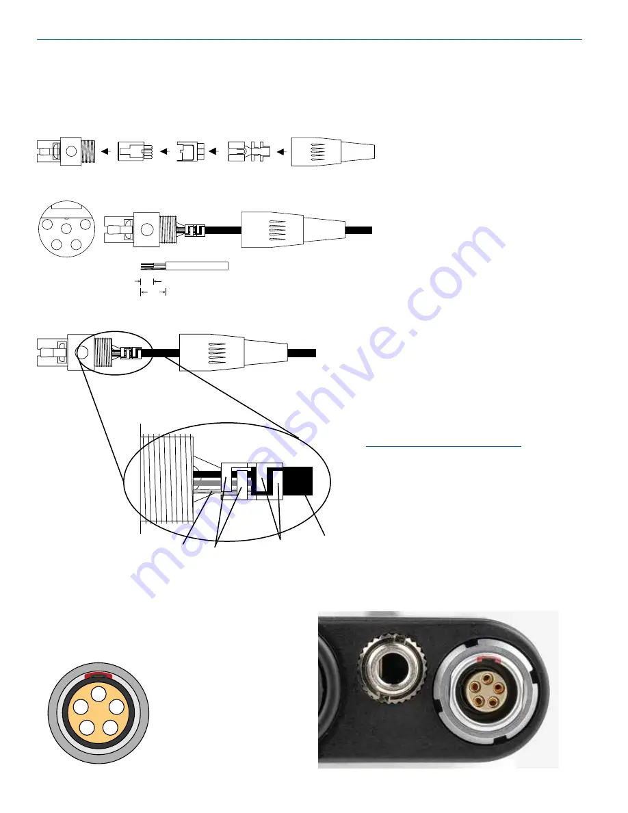
TA5F Connector Assembly

Mic Cord Stripping Instructions

1

2

3

4

5

VIEW FROM SOLDER

SIDE OF PINS

0.3"

0.15"

NOTE: This termination is intended for 

UHF transmitters and the MTCR only. 

VHF transmitters with 5-pin jacks require a 

different termination. Lectrosonics lavaliere 

microphones are terminated for compatibility 

with VHF and UHF transmitters, which is 

different from what is shown here.

Crimping to Shield and Insulation

Shield

Insulation

Strip and position the cable so that the clamp 

can be crimped to contact both the mic cable 

shield and the insulation. The shield contact 

reduces noise with some microphones and the 

insulation clamp increases ruggedness.

Crimp these 

fingers to 

contact the 

shield

Crimp these 

fingers to 

clamp the 

insulation

Timecode Jack Wiring

The timecode connection is made via a standard LEMO 

5-pin connector. Pin connections are as follows. Viewed 

from outside the connector.

1

2

3

4

5

1 - Ground
2 - SMPTE Timecode In
3 - Not used
4 - Not used
5 - Not used

Summary of Contents for MTCR

Page 1: ...good battery and turn the power on p 3 6 2 Insert microSDHC memory card and format it with the MTCR p 3 4 3 Timecode jam source p 7 8 4 Connect microphone or audio source 5 Set input gain Mic Level p...

Page 2: ...jack that accepts any mic or line level signal and provides bias voltage to power a wide variety of electret lavaliere microphones The input connection and wiring is compatible with microphones pre wi...

Page 3: ...luding 2 GB DO NOT USE SDHC high capacity more than 2 GB and up to and including 32 GB USE THIS TYPE SDXC extended capacity more than 32 GB and up to and including 2 TB DO NOT USE SDUC extended capaci...

Page 4: ...it freely iXML HEADER SUPPORT Recordings contain industry standard iXML chunks in the file headers with the most commonly used fields filled in Installing the Card The card slot is covered by a flexib...

Page 5: ...CD 40 20 0 REC i LAST T C00 01 33 Functions indicated by the icons on the LCD are activated by pressing the adjacent buttons on the keypad Icons in each corner of the LCD define the alternate function...

Page 6: ...blinks Recording Window To start recording press the REC button in the top right corner of the Main Window The screen will switch to the Recording Window NOTE The headphone output will be muted when r...

Page 7: ...SEL BACK MTCR Max Rec Time E F 0 14G Fuel gauge Storage used Storage capacity Available recording time H M S For information purposes only Bat Type SEL BACK SEL BACK Backlight SEL BACK Lock Unlock Mic...

Page 8: ...ould rarely be engaged but it will engage if necessary with no graphical indication to prevent clipping of the safety track NOTE See Record Mode HP Volume Use UP and DOWN arrows to adjust headphone vo...

Page 9: ...ble but any attempt to alter settings will prompt a LOCKED can use menu to unlock message The unit can be unlocked using the Lock Unlock setup screen The dweedle tone remote control will still work Ba...

Page 10: ...w button to begin the recovery process Recovery is nearly instantaneous When completed the display will show Recovery Successful 3 The recorder will boot up into the firmware update mode with the foll...

Page 11: ...ng the tab downward to the locked position prevents recording of data and protects existing data When recording to erasing from or formatting the MicroSD card slide the tab upward 4 If using a Windows...

Page 12: ...for Lectrosonics transmitters The screens appear differently for iOS and Android phones but perform the same functions For Best Results The following conditions are required The microphone must be wi...

Page 13: ...in 2 4 V PIN 5 Line level input for tape decks mixer outputs musical instruments etc Installing the Connector 1 If necessary remove the old connector from the microphone cable 2 Slide the dust boot on...

Page 14: ...s which is different from what is shown here Crimping to Shield and Insulation Shield Insulation Strip and position the cable so that the clamp can be crimped to contact both the mic cable shield and...

Page 15: ...alue can range from 2k to 4k ohms Fig 4 Fig 11 4 VOLT POSITIVE BIAS 3 WIRE ELECTRET NOTE This servo bias wiring is not compatible with earlier versions of Lectrosonics transmitters Check with the fact...

Page 16: ...elt clip snaps onto the housing M152 5P electret lavaliere microphone High perfor mance onmidirectional capsule locking 5 pin plug Switchcraft TA5F Additional Accessories MC35 line level adapter cable...

Page 17: ...e available re cording times are as follows The actual time may vary slightly from the values listed in the tables HD mono mode Size Hrs Min 8GB 11 12 16GB 23 00 32GB 46 07 Split gain mode Size Hrs Mi...

Page 18: ...MTCR LECTROSONICS INC 18...

Page 19: ...pair For timely service please follow the steps below A DO NOT return equipment to the factory for repair without first contacting us by email or by phone We need to know the nature of the problem the...

Page 20: ...sonics Inc will pay for the cost of returning your equipment to you This warranty applies only to items returned to Lectrosonics Inc or an authorized dealer shipping costs prepaid within one year from...

Reviews: