background image

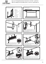
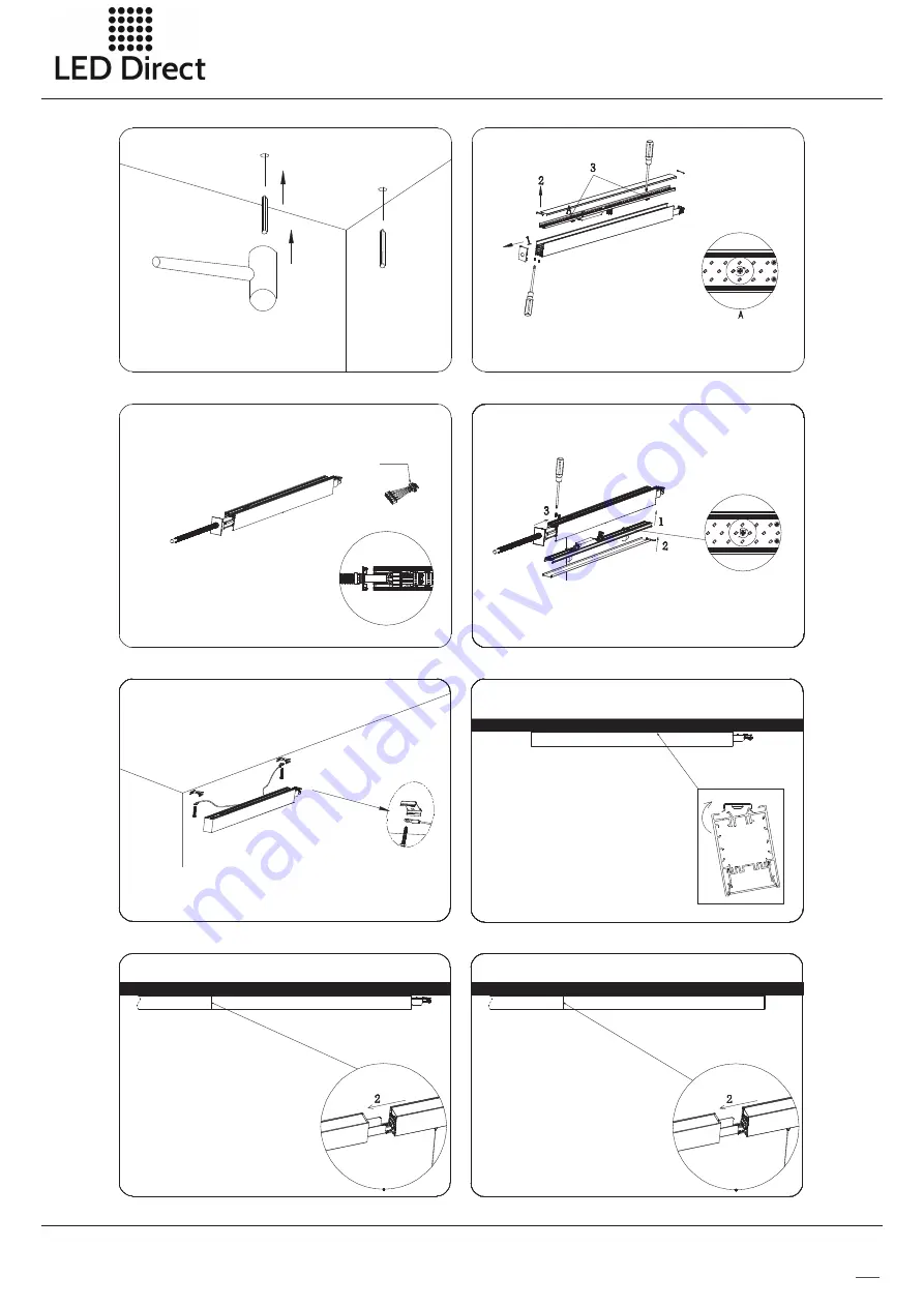
Install lampbody of the end run

1.Snap the clamp of suspendent rope into 
slot of lamp profile;
2.Insert  female connector of end run into 
male connector of previous run. 

Install lamp body of the middle run

1.Install ceiling lamp into profile slot of the 
middle run lamp;
2.Insert female connector of the first middle run
into the male connector of the first run ; and 
insert female connector of the next middle run 
into male connector of previous middle run. 
3. Splicing quantity
 When input voltage is 110V, N*P 

<

800W

 When input voltage is 277V, N*P 

<

2270W

 N is total run, and P is power of single lamp

P8

Install the first run lamp body

1. Install the cooling panel into shell of lamp body, and rotate  screws of 
fixing card clockwise by 90° to fasten the cooling panel into the lamp;
2. Press and mount the PC cover and inside cover plate on lamp;
3. Clip the end cap on the lamp,and fasten screws on the top of end cap.

1. Break through knockout hole on splicing profile;
2. Fix the 

conduit in the knockout hole;

3. Insert the female connector into male 
connector of lamp;
4. Thread AC connecting wire through 

conduit, 

and respectively connect N,GND,L, DIM+,DIM- of 
connector.nsion, and hammer the rubber plug into hole

connector 

Connect the input cable


Install the clamp of the first run lamp body

Thread the screw through fixing holes of safety rope and clamp, and 
fasten the screw with rubber plug in the ceiling


Install the first run lamp body

According to the figure, install the clamp on one 
side, then rotate and press mounting to another 
side of the clamp;

Drill hole

Drill hole according to corresponding dimension, 
and hammer the rubber plug into hole

Installation of the first run-disassemble lamp body

1. Unscrew the screws on the side of 

end cap with screwdriver;pull the end 
cap out by hand; 

2. Dismantle inner side cover and PC cover;
3. Rotate two screws of fixing card counter-clockwise by 90°, and 
dismantle cooling panel.

Kansas City:  735 Southwest Blvd Ste B • Kansas City, KS  66103  |   913.912.3760

   www.LED-KC.com   

Wichita:  327 N Hydraulic Ave, Ste 100 • Wichita, KS  67214 |   316.712.7614

   www.LED-Wichita.com

Summary of Contents for SL8456

Page 1: ...e power supply and lightingemitting parts PCB LEDs simple shape and random jointing can be realized IP40 waterproof it is can be widely used in home school shopping mall hotel and other indoor public placesand it is mainly made of aluminum alloy PC 5 8456 in single run 0 10V Dimming SL Kansas City 735 Southwest Blvd Ste B Kansas City KS 66103 913 912 3760 www LED KC com Wichita 327 N Hydraulic Ave...

Page 2: ...p and power supply is connected with high voltage live part via connector it is very convenient to install and disassemble and it is also safe and reliable to use 7 Multiple jointing can realized via 十 L shape connecting accessories SC SL8456 040 AW A02 03CW SC SL8456 040 AW A02 03NW SC SL8456 040 AW A02 03WW SC SL8456 075 AW A02 03CW SC SL8456 075 AW A02 03NW SC SL8456 075 AW A02 03WW 2835 2835 5...

Page 3: ... 03CW SC SL8456T 040 AW A02 03WW SC SL8456T 040 AW A02 03NW 5000K 3000K 4000K 216 216 216 4280lm 4120lm 4080lm AC100 277V 50 60Hz 0 10V Dimming 5 wires 14AWG copper core L N G DIM DIM Length feet 2 2 2 2 2 2 2 2 L shape lamp shape lamp Dimensions Unit mm inch All dimension tolerance is 2mm unless otherwise noted All dimension tolerance is 1mm unless otherwise noted 2400mm 94 48 Kansas City 735 Sou...

Page 4: ... see the steps on the continuous connection fix the end cap by screws and insert the inner end caps at both sides 1 SL8456 lamp boby 1pc 2 screws 2pcs 3 inner connector 1pcs 4 inner end cap 2pcs 5 end cap without knockout for suspending installation Or End cap with knockout for ceiling installation 1pc this end cap needs to be ordered separately 1pc Electrical Connection Kansas City 735 Southwest ...

Page 5: ...ixing head2 2PCS 11 rubber plug 2PCS 12 input wire 1PC 1 2 3 4 5 6 7 8 9 10 12 11 11 How to make the middle run loose the 2 screws at the lamp end and pull out the inner connector from the lamp body then fix the inner connector by 2 screws again insert the inner end caps at both sides How to make the last run Just fix the end cap at the last end by screws and insert the two inner end caps 1 SL8456...

Page 6: ... side cover and PC cover 3 Rotate two screws of fixing card counter clockwise by 90 and dismantle cooling panel Install shell of the first run lamp body 1 Thread square head screw through fixing hole of safey rope clamp then fasten it with wire lock 2 Snap the clamp into profile slot 3 Tightening the lamp with fixing head 1 and fixing head 2 Connect the input cable conduit connector 1 Break throug...

Page 7: ...nd run into male connector of previous run 3 Fasten the screws on joining with screwdriver Ceiling Installation Instructions of SL8456 Exploded drawing of the first run BOM 1 end cap of inlet wire 1pc 2 8456 lamp 1pc 3 4 25PA screw 2pcs 4 clamp 2pcs 5 rubber plug 2pcs 6 input wire 1pc Exploded drawing of the middle run BOM 1 8456 lamp 1pc 2 4 25PA screw 2pcs 3 clamp 2pcs 4 rubber plug 2pcs 33 refe...

Page 8: ... splicing profile 2 Fix the conduit in the knockout hole 3 Insert the female connector into male connector of lamp 4 Thread AC connecting wire through conduit and respectively connect N GND L DIM DIM of connector nsion and hammer the rubber plug into hole connector Connect the input cable Install the clamp of the first run lamp body Thread the screw through fixing holes of safety rope and clamp an...

Page 9: ...r qualified personnel to avoid dangers net weight pc 3 294kg gross weight CTN 16 631kg inner size 735 105 683mm carton size 750 225 701mm 2pcs inner box 2 inner boxes carton net weight pc 3 667kg gross weight CTN 9 818kg inner size mm carton size 647 225 584mm 1pcs inner box 2 inner boxes carton 632 105 566 1 2m lamp 2 4m lamp net weight pc 3 24kg gross weight CTN 24 8kg inner size 1274 130 106mm ...

Reviews: