33
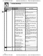
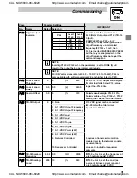
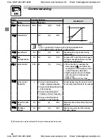
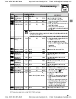
Commissioning
4.5.3
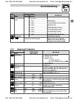
Advanced Setup Parameters
Code
Possible Settings
IMPORTANT
No.
Name
Default Selection
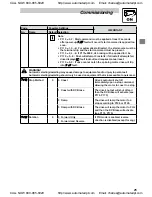
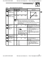
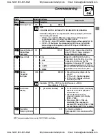
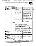
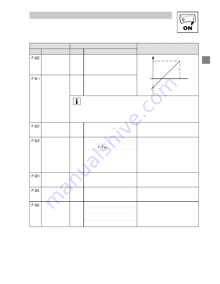
P160
Speed at
Minimum Signal
0.0
-999.0
{Hz}
1000
f
P161
P160
ref
10V
(20mA)
0V
(4mA)
V0111
P161
Speed at
Maximum Signal
60.0 -999.0
{Hz}
1000
Note
• P160 sets the output frequency at 0% analog input
• P161 sets the output frequency at 100% analog input
• P160 or P161 < 0.0 Hz: For scaling purposes only; does not indicate
opposite direction!
• P160 > P161: Drive will react inversely to analog input signal
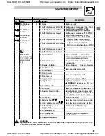
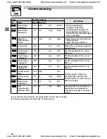
P162
Analog Input
Filter
0.01 0.00 {s} 10.00
Adjusts the filter on the analog inputs
(TB-5 and TB-25) to reduce the effect
of signal noise
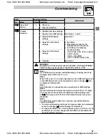
P163
TB-25 Loss
Action
0
0 No Action
• Selects the reaction to a loss of the
4-20 mA signal at TB-25.
• Signal is considered lost if it falls
below 2 mA
• Digital outputs can also indicate a
loss of 4-20 mA signal; see P140,
P142
1 Fault
F.FoL
2 Go to Preset when TB-25 is:
Speed reference: P137
PID feedback source: P137
PID setpoint reference: P233
Torque reference: P333
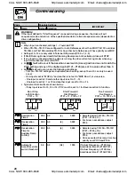
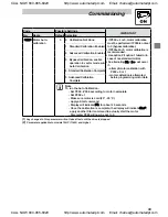
P164
TB-25 (4-20mA)
Analog Input
Monitoring Level
2.0
0.0 {mA} 10.0
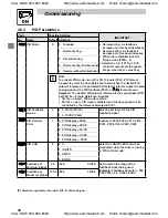
P165
Base Voltage
15 {V} 1000
Valid for V/Hz mode only.
Set voltage for bus compensation in
V/Hz mode
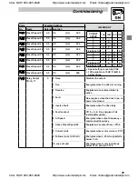
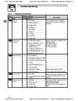
P166
Carrier
Frequency
1
0 4 kHz
• As carrier frequency is increased,
motor noise is decreased
• Observe derating in Section 2.2
• Automatic shift to 4 kHz at 120%
load
1 6 kHz
2 8 kHz
3 10 kHz
CALL NOW 800-985-6929
http://www.automatedpt.com
Email: charles@automatedpt.com
CALL NOW 800-985-6929
http://www.automatedpt.com
Email: charles@automatedpt.com


