background image


3.0 TRANSCEIVER (also referred to as receiver) 


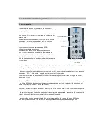
3.1 Normal Operation 


Immediately after connection of the supply voltage the receiver is in its normal operation mode (No push button may be 

pressed while starting this mode). In order to save battery capacity, the supply voltage should be taken off, when the 

receiver is not used. 
 
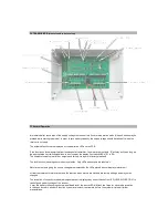
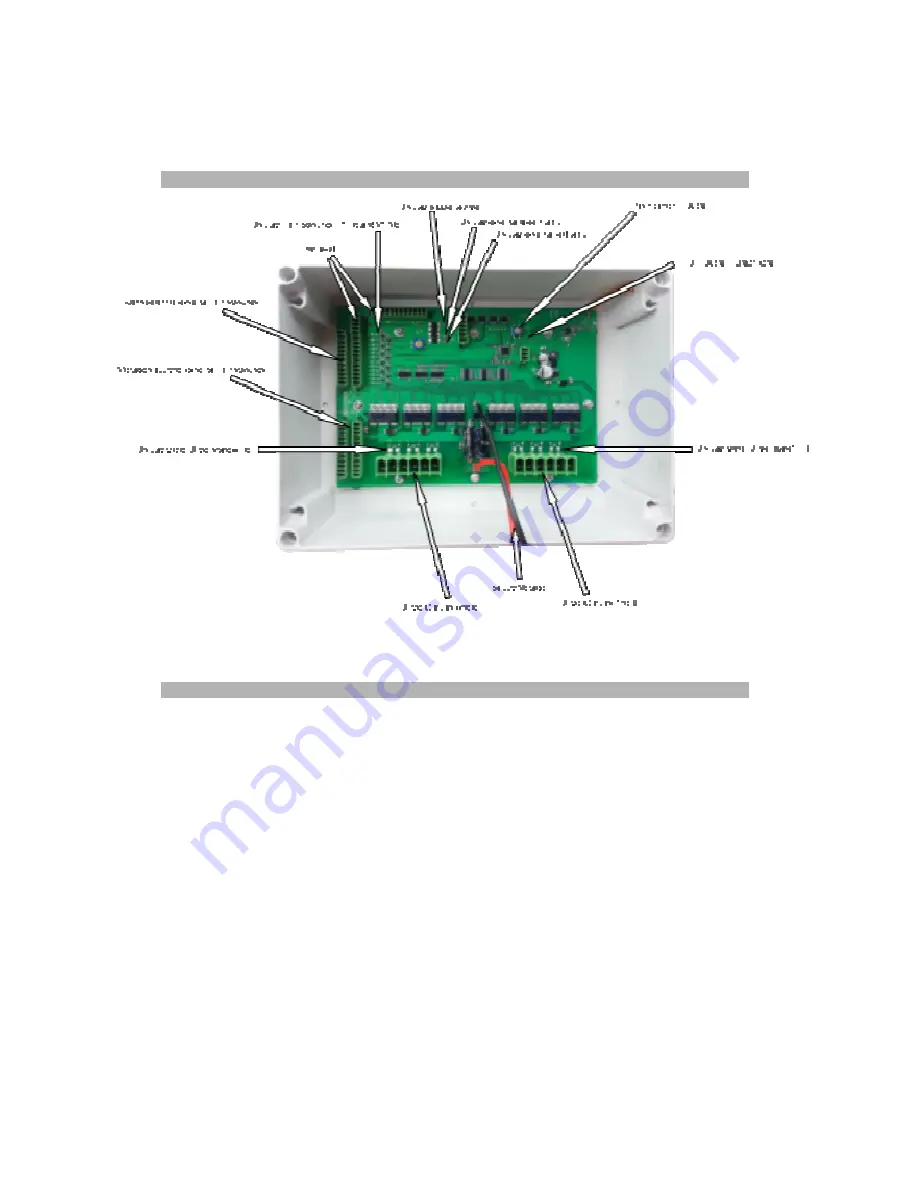
The activated functions are displayed by the dedicated LEDs on the PCB. 
 
If the function unlock was started from the handheld transmitter, the motor driver outputs “E” will stay active as long as 
the appropriated limit switch signalises to be closed by the display limit switch LEDs (E1 to E6). 
The number of usable motor driver outputs and limit switch inputs is factory predifined. 
 

The lock function is analogous to the unlock funtion. Only LEDs and outputs are labeled “V” 
 
Motor driver outputs giving the positiv voltage are displayed by the LEDs placed above (display motor driver) 
 
All start up features for motor driver and the reaction when motors are blocked are factory settings and may not be 
changed. 
 
The reception of correctly received radio signal packet is displayed by a short flash of the LED „LEARN/FUNCTION” in 
case of good battery voltage of the receiver.  
If ever this battery voltage drops below an allowed level, the above LED will flash two times for each radio reception. 
In this case there are another 5 function cycles (lock/unlock) that remain, before the system will stop all further 
manipulations. 

Summary of Contents for SH-12

Page 1: ...protection against harmful interference in a residential installation This equipment generates uses and can radiate radio frequency energy and if not installed and used in accordance with the instructions may cause harmful interference to radio communications However there is no guarantee that interference will not occur in a particular installation If this equipment does cause harmful interferenc...

Page 2: ...played by the 6 blue LEDs and the green LED stops flashing if the lock function is completed If lock or unlock function is activated but not yet completed both of them may be interrupted at any time by pressing push button 4 STOP This results in stopping all motor outputs at receivers side While the stop command is transmitted to the receiver the red and the green LED will flash as long as the sig...

Page 3: ...ted frequency channel is stored The receiver needs not to be changed It will automatically synchronize to the selected transmitter frequency 2 3 Technical Details Frequency channel 1 910 000 MHz factory setting channel 2 910 300 MHz channel 3 910 600 MHz channel 4 910 900 MHz Supply 4 5 V DC 3 alkaline batteries type AAA Dimension 120x70x30mm Manipulation 4 push buttons 2 x ENABLE within 0 5 s ena...

Page 4: ...e number of usable motor driver outputs and limit switch inputs is factory predifined The lock function is analogous to the unlock funtion Only LEDs and outputs are labeled V Motor driver outputs giving the positiv voltage are displayed by the LEDs placed above display motor driver All start up features for motor driver and the reaction when motors are blocked are factory settings and may not be c...

Page 5: ...h address the LED LEARN FUNCTION flashes slowly 3 times to signalise the non accepted new device In this case all learned addresses must be erased Therefore press the push button LEARN once as you do for entering into the learn mode and then press again and hold the same pushbutton for at least 5 seconds The learn mode will then be left automatically If the learn mode has been activated accidental...

Reviews: