background image

Owner’

Levelwind

Air & Water Hose Reels Parts &  
Technical Service Guide

1

Legacy Manufacturing Company


Marion, IA 52302 USA

Ph:  319.373.7305  
Fx:  319.373.7309

service@legacymfg.com
legacymfg.com

INS8306-0204

(Published 12/19/2016


Revised 06/25/2020) 

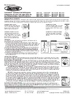
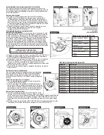
Mounting Options:

CAUTION: Maximum installation height is 15 ft. (4.5 meters) above ground. Maximum weight of hose end tools is 4 lb. (2 kg) . Maximum working pres-
sure is 350 PSI (24 bar). (140 PSI (9.65 bar) for Models L8346, L8349 & L8350). 300 PSI (20.68 bar) for Model L8335. Do not stand or step on top of reel!

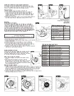
Mounting to wall

Positioned up to 5 ft. (1.5 m) high. Use 
standard replacement part
L8300-W Wall / Overhead bracket.


High Wall Mounting

Mount reel between 10 ft. and 15 ft.
(3-4.5 m) high on wall. Use optional 
Bench / High Wall mounting bracket 
Model L8300-B.

Mounting overhead

Up to 15 ft. (4.5 m) from floor. Use 
standard replacement part L8300-W 
Wall / Overhead bracket.

Mounting to a bench

Use optional Bench / High Wall 

racket model L8300-B.

Installation:
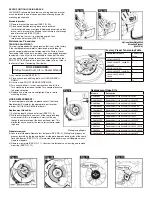
LEVELWIND retractable hose reels are designed for minimum assembly.
1) Place bracket on a flat mounting surface. With a pencil trace bracket back holes

onto surface. Use a leveling device to ensure that the bracket will be level once,
fastened. Fasten brackets to surface with screws (screws are not included).

2) Remove bracket rod (A) from bracket (B) (SEE FIG. 1).
3) Place reel into bracket making sure the reel hole is aligned with bracket end holes.
4) Insert bracket rod through the aligned holes of reel and bracket. Insert hitch-pin

clip through end of bracket rod.

5) Connect female end of lead-in hose to inlet connection on reel. Connect male end

to air or water source (SEE FIG. 2).

Operating Instructions:

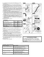
LEVELWIND retractable hose reels can operate in FREERUN or can be latched every 3 ft. (91 cm) by switching to the LATCHING ZONE. Simply turn the 
mode switch to desired position (SEE FIG. 3).

THE “

LATCHING ZONE

”: LEVELWIND reels have a single latching zone. The reel can be latched for every drum revolution approx. 

3 ft. (91 cm) of hose. There are audible clicking sounds as the spring loaded latch passes over the latching zone. The latching zone 
flips the latch so that the latch goes into or by-passes the latching position. Pulling hose straight out off the reel “flips the latch” so it 
can go into the latching position. Retracting the hose into the reel keeps the latch “flipped” so that the latch by-passes the latching 
position.

LATCHING -

 Pull out the desired length of hose. As you are pulling out hose from the reel, listen for a “click”. STOP! Don’t 

pull any further! If you keep pulling out hose (more than 14 in. (36 cm)) after hearing the “click”, you will have pulled past the 
latching zone. Now, allow the hose to go back into the reel (less than 14 in. (36 cm)) and the latch will drop into the latching 
position. The reel is now latched!

RETRACTING -

 Assuming the latch is engaged in the latching position, pull out hose until you hear a “click” (approx. 14 

in. (36 cm)). STOP! Don’t pull any further! If you pull out more than 3 ft. (91 cm) of hose after hearing the “ click”, you will have 
gone a full drum revolution and back into the latching zone where the reel will once again be latched. Now, allow the hose to 
retract back into the reel.
The hose reel will continue retracting hose until it is fully retracted. If you decide to re-latch the reel while you are still retract-
ing hose, simply listen for a click. STOP! Slowly pull out hose until you hear a second click. STOP! Don’t pull any further. Now, 
slowly allow the hose back into the reel (less than 14 in. (36 cm)) and the latch will drop into the latching.

FREERUN MODE:

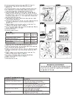
 The hose does not latch in this mode. Hose will automatically retract back into reel. The hose stopper position 

may be adjusted to desired length for application (SEE FIGURE 4) 

CAUTION!

 Do not release the end of the hose when rewinding 

as personal injury or damage could result!

Model L8305
Model L8305FZ
Model L8306
Model L8306-EU

Model L8306FZ
Model L8310
Model L8310-EU
Model L8335

Model L8335-EU

Model L8340FZ

Model L8335FZ

Model L8344

Model L8345
Model L8346
Model L8349
Model L8350

s Instructions

 Retractable

mounting b

The color CHARTREUSE as applied to the body of the air and water hose is a registered trademark owned by Weems Industries, Inc.

Flexzilla is a registered trademark owned by Weems Industries, Inc.  Levelwind is a trademark owned by Weems Industries, Inc.

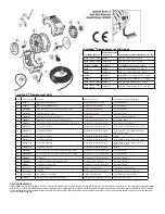
Summary of Contents for Levelwind L8305

Page 1: ...s over the latching zone The latching zone flips the latch so that the latch goes into or by passes the latching position Pulling hose straight out off the reel flips the latch so it can go into the latching position Retracting the hose into the reel keeps the latch flipped so that the latch by passes the latching position LATCHING Pull out the desired length of hose As you are pulling out hose fr...

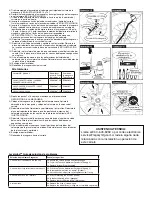
Page 2: ...tension Turn counterclockwise to decrease tension 5 Replace hub plate screws and tighten Return reel to mounting bracket Factory Preset Tensioning Table HOSE REPLACEMENT To ensure proper performance please consult the Hose Replacement Kit table for the appropriate part number to order Call 1 800 645 8258 to order kit Replacement Hose Kits 1 Pull entire length of hose out of reel SEE FIG 8 2 While ...

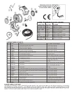
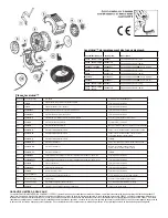
Page 3: ... 2 Place hose onto hose barb of new swivel body Tighten hose clamp onto hose place swivel into hose spool housing 3 Replace wear ring and fasten with wear ring screws Replace wear plate so that the swivel drive tabs insert into wear plate tab receivers SEE FIG 18 4 Replace sideplate so that the plate snaps flush to side of reel Turn sideplate until locking tabs connect to sideplate 5 Turn swivel s...

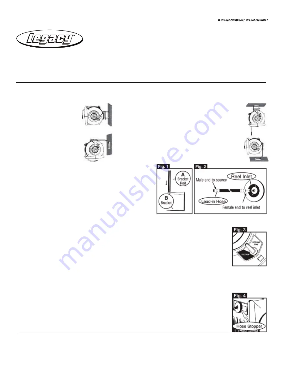
Page 4: ... L8346 L8347 L8349 6c RP005010 18 Layering Device Assembly The layering mechanism doesn t operate L8340FZ 7b RP005012 140 Layering Device Drive Belt The layering mechanism doesn t operate L8305 All Models L8306 All Models L8310 All Models I L8345 I L8350 8a RP005004BK Latch Switch Side Plate w Latch Spring Pawl Mechanism Black The hose does not lock the desired length All LevelwindTM Models 7c RP0...

Page 5: ...l tirar de la manguera directamente del carrete coloca el fiador por su lado contrario de manera que se bloquee Al retraer la manguera en el carrete se mantiene el fiador en su posición inversa de manera que el pestillo no se bloquee LATCHING posición de bloqueo Tire de la manguera a la longitud deseada Mientras tira de la manguera en el car rete escuche un chasquido DETÉNGASE No tire más de la ma...

Page 6: ...la tensión Gírela en el sentido opuesto de las manecillas del reloj para dis minuir la tensión 5 Reinstale los tornillos de la placa y apriételos Reinstale el carrete en el portacarrete Series LevelwindTM Modelo Núm de Giros Tabla de la Fuerza de Tensión REPOSICIÓN DE LA MANGUERA Con el fin de garantizarle el rendimiento funcional adecuado por favor consulte la tabla que indica el número apropiado...

Page 7: ...e del ensamble del columpio y extráigalo del carrete de la manguera VER ILUSTRACIONES 13 y 14 6 Destornille la abrazadera de la manguera y extraiga la espiga de la manguera en el columpio VER ILUSTRACIÓN 15 7 Tire de la longitud restante de la manguera hacia fuera de la abertura del carrete en la parte del frente 8 Inserte la manguera a través de la abertura ubicada al frente del carrete Guíe la m...

Page 8: ...aca lateral del columpio negra RP005002BK Todos los modelos de Levelwind Conjunto de cuerpo giratorio basado en el diámetro interior RP005007 xx Consulte Diagrama de tope de manguera y pivote de repuesto Ensamble del tambor para mangueras RP005015 Modelos 50 Levelwind RP005004GRNT Lengüeta lateral del interruptor de cierre con muelle de retención y mecanismo de trinquete Granito Todos los modelos ...

Page 9: ...n de verrouillage ou évite cette position Une traction sur le tuyau directement hors du dévidoir fait basculer le verrou de manière à ce qu il puisse passer en position de verrouillage La rétraction du tuyau dans le dévidoir garde le verrou basculé de manière à ce que le verrou évite VERROUILLAGE Tirer la longueur désirée de tuyau Pendant la traction du tuyau dès que le déclic correspondant à la l...

Page 10: ...é dans le sens anti horaire 5 Remettre les vis du plateau de moyeu en place et les serrer Remonter le dévidoir sur son support de montage Série LevelwindTM modèle Nombre de tours Table de serrage en usine REMPLACEMENT DU TUYAU Pour obtenir des prestations appropriées prière de consulter le tableau de nécessaires de remplacement de tuyau pour connaître le bon numéro des pièces à commander Composer ...

Page 11: ...tionnement de ce dévidoir 5 Tirer l ensemble de pivot fermement hors de la bobine de tuyau VOIR FIG 13 et 14 6 Dévisser la bride de tuyau et tirer le tuyau hors de la barbe de tuyau sur le pivot VOIR FIG 15 7 Tirer la longueur restante de tuyau hors de l ouverture avant du dévidoir 8 Faire passer le tuyau de rechange à travers l ouverture située à l avant du dévidoir Faire passer le tuyau à traver...

Page 12: ...evelwind L8300 B Support de fixation de banc haut mur Tous les modèles Levelwind RP005000BK Tous les modèles Levelwind RP005002BK Tous les modèles Levelwind Ensemble de corps pivotant basé sur le diamètre intérieur RP005007 xx Voir pièces d arrêt Schéma de tuyau et pivot Ensemble de tambour pour tuyau RP005015 Les modèles 50 Levelwind RP005004GRNT Plaque latérale de verrouillage avec ressort de ve...

Reviews: