background image

11

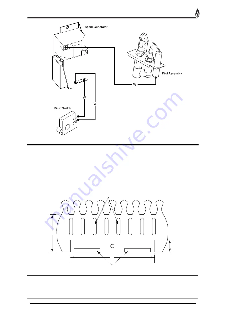
Fire fronts are now available in many different designs and finishes. The user can now choose their own
particular style of fire front to suit their individual fireplace setting, providing the fire front complies with the
following dimensions -

Fire Front - 

(X) Max: 210mm

Min: 190mm

Ash Pan Cover -

(W) Max: 90mm

Min: 65mm

(Y) Max: 345mm

Min: 320mm

SAFETY WARNING - This appliance has a naked flame and as with all heating appliances a fireguard
should be used for the protection of children, the elderly and infirm. Fireguards should conform to
BS 6539 (1984 Fireguards for use with solid fuel appliances). This fire is not fitted with an integral
guard. In normal use consideration may be given to the use of a fireguard confirming to BS 6539,
such that the approach to the naked flame is minimised.

IGNITION SYSTEM WIRING DIAGRAM

FIRE FRONT SPECIFICATIONS

w

Y

X

Minimum area free space 15cm

2

Minimum area free space 5cm

2

Fig. 11

Fig. 10A

Summary of Contents for Spirit Superslim

Page 1: ...and then should be handed to the end user when the installation is complete This is an official requirement and is the responsibility of the fitter of this appliance Having installed the appliance the installer should take the necessary steps to ensure that the user fully understands how to operate the appliance and is also made aware of the fire s basic cleaning and maintenance requirements ...

Page 2: ...missioning 6 Technical Data 7 Replacement Parts 7 Trouble Shooting GAS SAFE Engineer Only 8 User Instructions 9 Cleaning and Maintenance 10 Ignition System Wiring Diagram 11 Fire Front Specifications 11 Coal Layout Instructions 12 Pebble Layout Instructions 14 Guarantee 16 Trouble Shooting User 16 CONTENTS 2 ...

Page 3: ...open position The chimney flue must always generate a positive up draught to ensure safe operation The installer must then establish that all the products of combustion are entering the flue within five minutes of lighting from cold This can be verified by traversing the canopy with a lighted smoke match see Spillage Test page 4 An isolation valve must be fitted adjacent to the appliance When clos...

Page 4: ...e increased by 25mm for each additional 12 5mm of profile depth FLUE FLOW TEST A flue flow test smoke test is carried out to check the effectiveness of the flue and to ensure that there is no leakage into another part of the premises including any loft or as appropriate other adjoining premises this is particularly important where a number of chimneys combine into a multiple stack The flue flow te...

Page 5: ...o the box two on the front leg and two at the rear of the tray Remove the burner tray and place to one side Fig 3 6 When the burner tray has been removed decide which side of the appliance the gas supply will be entering the radiant box and remove the relevant blanking plate left or right hand side The gas supply should be concealed as much as possible 7 With the radiant box placed in the opening ...

Page 6: ...arry out a gas soundness test 1 Unscrew the pressure test point sealing screw Fig 7 and fit a manometer Consult the user instructions page 9 Ignite the appliance and turn to the high position 2 Take a pressure reading and consult the technical data page 7 to establish the correct working pressure 3 Once the pressure has been checked and verified turn off the appliance Consult the ceramic component...

Page 7: ...he consumer can do so provided that the Ceramic Component Layout Instructions pages 12 15 are adhered to Only genuine Legend replacement parts should be used Order Ref SSFC02 SSCM03 2 Oxygen Depletion Sensing Pilot In the unlikely event of a pilot failure the pilot assembly should only be replaced by a GAS SAFE Registered Engineer The user must not carry out this work Order Ref LEG01 3 Control Tap...

Page 8: ...elay the coal set as per Ceramic Component Layout Instructions pages 12 15 5 The fire makes a roaring noise when lit Check That the front coal is seated correctly and the pilot hole is positioned correctly over the pilot assembly IF ANY PART OF THE PILOT ASSEMBLY IS SUSPECTED AS BEING FAULTY THE COMPONENT MUST BE REPLACED 6 The flames appear blue after the fire has fully warmed up The coals cerami...

Page 9: ...ted back up to the minimum setting 6 To switch off the appliance completely simply lift the lever fully to the top position Note The pilot assembly fitted to this appliance has an oxygen depletion sensor built in to monitor the room for products of combustion If the sensor should operate and switches the appliance off re ignite the appliance following the procedure above Should the appliance repea...

Page 10: ...mponents as they will break if handled incorrectly Do not use a vacuum cleaner to clean the ceramics 2 Radiant Box Ceramic Liners Use only a soft brush to remove any soot deposits from the ceramic liners during cleaning as this is the only method that can be used to remove deposits The ceramic liners are very delicate and should be treated accordingly 3 Brass Trims and Frets The brass trim and fre...

Page 11: ...pliance has a naked flame and as with all heating appliances a fireguard should be used for the protection of children the elderly and infirm Fireguards should conform to BS 6539 1984 Fireguards for use with solid fuel appliances This fire is not fitted with an integral guard In normal use consideration may be given to the use of a fireguard confirming to BS 6539 such that the approach to the nake...

Page 12: ...ng sure that the back edge is pushed up against the front of the burner strip Fig 13 CAUTION The coals are extremely fragile and must be handled accordingly Gloves should be worn and any inhalation of dust should be avoided Never put additional coals on the fire Never use coals other than those originally supplied or genuine Legend Spare Parts Fig 12 Fig 14 Fig 15 Fig 13 Burner Strip Fuel Bed 4 Lo...

Page 13: ... shown in order to achieve the desired flame picture It may be necessary to remove some or all of the coals to clean them at some time Cleaning must only be done using a soft brush Ceramic touch up dye is available from Legend Fires 5 Finally check that all the coal pieces are nested together correctly Fig 16 ...

Page 14: ... sure that the back edge is pushed up against the front of the burner strip Fig 18 CAUTION The pebbles are extremely fragile and must be handled accordingly Gloves should be worn and any inhalation of dust should be avoided Never put additional pebbles on the fire Never use pebbles other than those originally supplied or genuine Legend Spare Parts Fig 17 Fig 19 Fig 20 Fig 18 Burner Strip Fuel Bed ...

Page 15: ... shown in order to achieve the desired flame picture It may be necessary to remove some or all of the pebbles to clean them at some time Cleaning must only be done using a soft brush Ceramic touch up dye is available from Legend Fires 5 Finally check that all the pebble pieces are nested together correctly Fig 21 ...

Page 16: ...oose coals and the front coal and thoroughly clean any debris in and around the pilot area If the fire will still not light contact your installer 2 The flames appear blue excessive soot deposits The ceramic components including the coal need relaying pages 12 15 Too much or too little room ventilation Seek professional advice 3 Roaring noise coming from the pilot The front coal is not seated corr...

Reviews: