


45
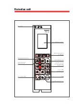
Protection unit
10. Logical selectivity
The feature logical selectivity is not supported by PU versions ref . 0 281 67 / 0 281 68 .
For the General indications and requirements about the function Logical Selectivity refer to standard
Logical Selectivity Guide .
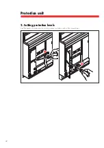
Connection terminals:
Please refer to breaker installation manual .
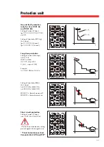
Activation:
The input/output connections for logical selectivity can be activated by modifying the protection unit
settings navigating in menu as specified below:
Setting
➔
Relay Settings
➔
Function Settings
➔
choose "SEL IN" in contact list
➔
select "ON" in the
function list (not required for the last downstream selectivity level - D)
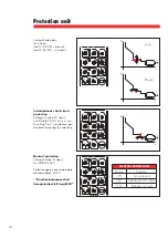
Setting
➔
Relay Settings
➔
Function Settings
➔
choose ”SEL OUT" in contact list
➔
select "ON" in
the function list (required for all selectivity levels - A/B/C/D)
Wiring and Supply:
Please remind the protection unit always needs to be supplied by a specific external module
ref . 0 281 72 in order to provide a correct working of logic selectivity .
In addition,the input of the logic selectivity (DI) also needs to be supplied at 24V DC voltage on its
terminals . In detail,the positive polarity of su( 24V) must be connected to terminal H11 .
This supply can be provided by the same module ref . 0 281 72 which supplies the PU .
On the contrary, the output of the logic selectivity (DO) doesn't require an additional supply .
Summary of Contents for 0 281 64
Page 1: ...Unité de Protection Juin 17 LE08438AB Réf 0 281 64 65 66 67 68 ...
Page 2: ......
Page 27: ...Protection unit June 17 LE08438AB References 0 281 64 65 66 67 68 ...
Page 28: ......
Page 53: ...53 Protection unit ...
Page 54: ...54 Protection unit ...
Page 55: ...55 Protection unit ...
Page 56: ...LE08438AB ...


