Daker DK 1, 2, 3 kVA
33
EN
On the rear of the uninterruptible power supply are the following connections:
• Output sockets [19] input connector [18]: connect to these connectors the power cable and the
output cables included.
• Socket for connecting computer serial interface RS232 (9 female pins) [14]: required when using
the diagnostic and shutdown management software.
• Socket for USB interface connection [13]: to be used when connecting the UPS using a USB cable.
• Presetting for the connection of additional batteries [17].
WARNING
For safety reasons it is advised not to modify the cables supplied; it is also necessary to make
sure that that the mains socket the uninterruptible power supply is connected to is fitted
with a safe connection to the earth system, and appropriate protection in accordance with
current regulations.
WARNING
The mains supply socket, or the disconnection device, must be installed nearby the
equipment, and must be easily accessible.
Proceed to the installation as follows:
1) Position the uninterruptible power supply so that the vents are not obstructed.
2) Connect the input connector [18], the power cable, and the output cables to the appropriate
connectors [19].
3) Connect the loads to the output cables, ensuring that the switches of the various users are off.
4) Connect the power supply plug to a power socket with suitable voltage and current.
Start
1) Switch on the power breaker [ 21 ] of the distribution panel. Then the UPS will start up. Green
LEDs
, and
and show that the Utility and Bypass inputs are normal. The LCD will
display OFF after few seconds.
2) The UPS is in Bypass Mode now. It will proceed to self-test automatically. If no abnormal message
appears then the pre-startup of the UPS was successful and the charger starts to charge the
batteries.
3) Press the UPS On Switch
[ 7 ] for approximately three seconds. The Buzzer sounds twice and
the LCD display changes from previous status to RUN mode.
4) The UPS is in self-test mode again. The LCD display will show TEST and the UPS will remain in
battery mode for approximately four seconds.
5) If the self-test fails an error code or error status will appear on the screen.
6) Your start-up operation of the UPS is complete now. Make sure the UPS is plugged into the wall
receptacle for charging at least 8 hours and the batteries are fully charged before connecting
the device to be protected.
Summary of Contents for 0 3 100 51
Page 1: ... Part LE05334AC 07 13 01 GF Daker DK 1 2 3 kVA Manuel d installation Installation manual ...
Page 8: ...Daker DK 1 2 3 kVA 29 EN Tower configuration setup A1 A1 A1 A1 A3 A2 Step 1 Step 2 ...
Page 9: ...30 4 Installation UPS battery cabinet optional A4 Step 1 Step 2 ...
Page 10: ...Daker DK 1 2 3 kVA 31 EN B2 B1 S3 90 Step 1 Step 2 Step 3 Step 4 ...
Page 11: ...32 4 Installation Step 5 Step 6 ...
Page 14: ...Daker DK 1 2 3 kVA 35 EN R1 R2 S T U1 U2 U3 V ...
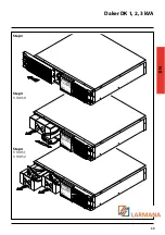
Page 17: ...38 6 Battery replacement Step 1 Step 2 ...
Page 18: ...Daker DK 1 2 3 kVA 39 EN Step 3 Step 4 3 100 50 Step 4 3 100 51 3 100 52 ...


