background image

5/5 


STOP & GO automatic 

STOP & GO automatic 

STOP & GO automatic 

STOP & GO automatic resetting

resetting

resetting

resetting


Cat. N°(s)

Cat. N°(s)

Cat. N°(s)

Cat. N°(s)    : 4

: 4

: 4

: 4    062 88 / 89

062 88 / 89

062 88 / 89

062 88 / 89 


5. GENERAL CHARACTERISTICS 

5. GENERAL CHARACTERISTICS 

5. GENERAL CHARACTERISTICS 

5. GENERAL CHARACTERISTICS 

(continued)


Resistance to sinusoidal vibrations:

Resistance to sinusoidal vibrations:

Resistance to sinusoidal vibrations:

Resistance to sinusoidal vibrations:    

. According to IEC 60068-2-6. 
. Axis : x, y, z. 
. Frequency range: 5÷100 Hz ; duration 90 min. 
. Displacement (5÷13.2 Hz) : 1mm 
. Acceleration (13.2÷100 Hz) : 0.7g (g=9.81 m/s

2

). 

Maximum power consumption:

Maximum power consumption:

Maximum power consumption:

Maximum power consumption:    

. <20VA rms (<80VA peak) during resetting 

Standby power consumption:

Standby power consumption:

Standby power consumption:

Standby power consumption:    

. <1,5VA 

Recognition:

Recognition:

Recognition:

Recognition:    

. Labelling of the circuits by label in the "label holder" on the front-side of the device. 

6. CO

6. CO

6. CO

6. CON

N

N

NFORMITIES AND APPROVALS

FORMITIES AND APPROVALS

FORMITIES AND APPROVALS

FORMITIES AND APPROVALS    

Compliance with

Compliance with

Compliance with

Compliance with standard

 standard

 standard

 standardssss::::    

. CEE guidelines : 73/23/CEE + 93/68/CEE 
. IEC / EN 50557: device for automatic reset of MCB’s, RCBO’s, RCCB’s for household and similar purposes. 

. Electromagnetic compatibility: EN 61543  
. Legrand devices can be used under the conditions of use as defined by IEC / EN 60947. 

7. 

7. 

7. 

7. AUXILIARIES

AUXILIARIES

AUXILIARIES

AUXILIARIES AND  ACCESSORIES

 AND  ACCESSORIES

 AND  ACCESSORIES

 AND  ACCESSORIES    

Signal

Signal

Signal

Signalling

ling

ling

ling auxiliaries:

 auxiliaries:

 auxiliaries:

 auxiliaries:    

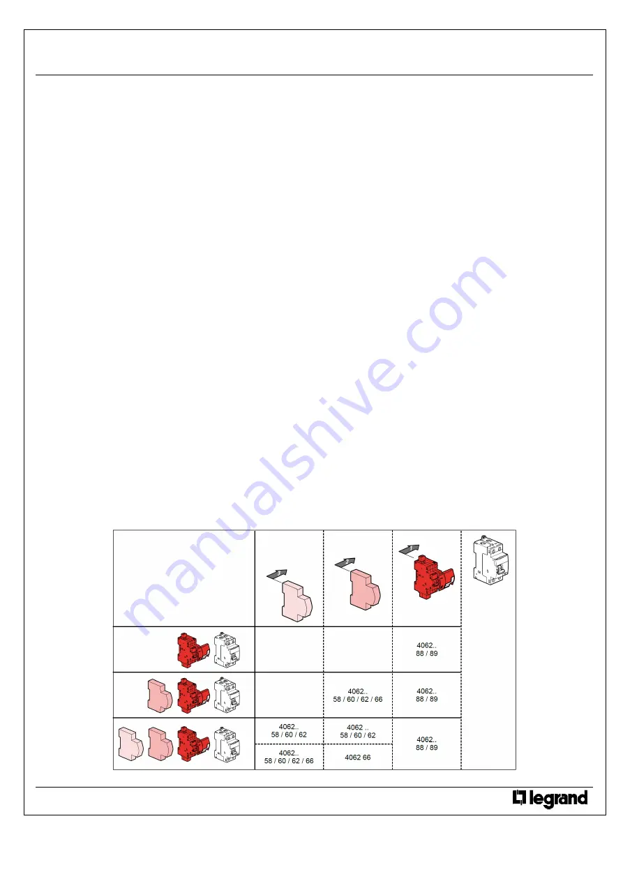
. Auxiliary contact (½ module – cat n° 4 062 58). 
. Fault signalling changeover switch (½ module – cat n° 4 062 60). 
. Auxiliary contact modifiable in default signal (½ module – cat n° 4 062 62). 
. Auxiliary c fault signalling switch - can be modified to 2 auxiliary contacts (1 module - cat n° 4 062 66). 

Control auxiliaries:

Control auxiliaries:

Control auxiliaries:

Control auxiliaries:    

. It is forbidden to associate control auxiliaries (cat. n° 4 062 7x / 8x) to motor driven control module with integrated automatic resetting. 

Possible combinations with

Possible combinations with

Possible combinations with

Possible combinations with signal

 signal

 signal

 signalling

ling

ling

ling auxiliaries:

 auxiliaries:

 auxiliaries:

 auxiliaries:    

. Auxiliaries are clipped on the left side of the Stop & Go unit 
. Two signalling auxiliaries max. (cat. n° 4 062 58 / 60 / 62 / 66). 
. If two signalling auxiliaries are associated to a same motor driven control unit, the 1 module wide control auxiliary (cat n° 4 062 66 / 78 / 82 / 84) 
must be located to the left of the ½ module wide auxiliary (cat. n° 4 062 58 / 60 / 62). 


Technical data sheet: F01284EN/00 

Updated: - 

Created: 11/11/2011 


Summary of Contents for 4 062 88

Page 1: ...lock for small or large model For locking the handle of the modular devices MCBs RCCBs RCBOs or isolating switches in OFF position Voltage surge protectors p 66 70 4 063 19 Keor UPS p 678 Pack Cat Nos Connected STOP GO remote control resetting For remotely switching via a smartphone or tablet 1 module per pole RCCBs and RCBOs up to 63 A Examples of use In the event of unwanted tripping generated b...

Page 2: ...liaries 71 5 8 8 17 7 61 83 44 77 7 84 5 DX3 remote control 74 3 17 7 35 4 61 83 44 80 5 98 8 DX3 Stop Go automatic resetting 74 3 35 4 61 83 44 80 5 113 7 Change over switches 68 17 7 35 6 60 83 44 74 94 CX3 latching relays 64 17 8 17 8 35 6 35 6 61 84 5 44 70 2 94 8 CX3 contactors up to 25A 66 3 61 17 8 17 8 35 6 35 6 61 84 5 44 72 6 67 3 94 8 CX3 contactors 40A 63A 62 35 6 53 4 53 4 60 83 44 68...

Page 3: ...t protect the installation against lightning strikes For an efficient protection against lightning use voltage surge protectors The Autotest version is specially suitable for installations equipped with residual current protection devices RCD s and RCBOs STOP GO periodically does an automatic test of the functionning of residual current protection devices The manual test is no longer needed Alarm ...

Page 4: ...ry handles SD 406260 Front external handle Cat No 4 063 19 20 Extension supplied with the external handle Cat No 4 063 19 20 Auxiliary contact 4P DX3 MCB Padlock Cat No 4 063 13 not supplied n Example of mounting on a DX3 MCB ...

Page 5: ...N Cat N 4 4 4 4 062 88 062 88 062 88 062 88 It automatically resets the associated device P N or 2P in case of tripping after a transient fault It checks the status of the installation before to reset It reports any permanent fault earth leakage or short circuit Cat N Cat N Cat N Cat N 4 4 4 4 062 89 062 89 062 89 062 89 In addition to the same functions as cat n 4062 88 it allows an automatic per...

Page 6: ...TION continued Stripping length recommended Stripping length recommended Stripping length recommended Stripping length recommended 7 mm Screw head Screw head Screw head Screw head Slotted diameter 3 5 mm Recommended tightening torque Recommended tightening torque Recommended tightening torque Recommended tightening torque 0 4 0 5 Nm Tools required Tools required Tools required Tools required For t...

Page 7: ...nt fault has disappeared the resetting of the Stop Go and of the associated device is carried out by the Stop Go handle isolating and power handles together Selector AUTO MAN Selector AUTO MAN Selector AUTO MAN Selector AUTO MAN The selector enables and disables the automatic remote control Positions AUTO possibility to automatically or manually control tripping and re setting MAN manual control o...

Page 8: ...c strength lectric strength lectric strength lectric strength 2500 V Mechanical endurance Mechanical endurance Mechanical endurance Mechanical endurance 20000 operations Electrical endurance Electrical endurance Electrical endurance Electrical endurance In accordance with the requirements of the standards of the associated protection device Enclosure material Enclosure material Enclosure material ...

Page 9: ... reset of MCB s RCBO s RCCB s for household and similar purposes Electromagnetic compatibility EN 61543 Legrand devices can be used under the conditions of use as defined by IEC EN 60947 7 7 7 7 AUXILIARIES AUXILIARIES AUXILIARIES AUXILIARIES AND ACCESSORIES AND ACCESSORIES AND ACCESSORIES AND ACCESSORIES Signal Signal Signal Signalling ling ling ling auxiliaries auxiliaries auxiliaries auxiliarie...

Page 10: ...7 mm 3 5 mm 0 5 Nm max Ø 4 mm 4 062 89 30 mA 16 A In 100 A 63 A DX3 10000 G O MAX 2 5 mm 2 2 x 1 5 mm2 Pz 1 17 5 mm 17 5 mm 2P Hpi ʌ 1P N 2P 63 A 2 8 Nm max 1P N N0265B LE04414AB 4 062 88 89 09 12 01 WP ...

Page 11: ...ición ON pasar el selector de la posición AUTO a la posición MAN y volver a pasarlo a la posición AUTO 2 El primer test automático de la función diferencial es instantáneo El siguiente test se realizará 56 días y 8 horas después de reali zarse el primero y permitirá decalar este test a las horas nocturnas los tests sucesivos se realizarán cada 56 días 8 semanas Programação 1 Após colocar sob tensã...

Page 12: ...3 Auto test 4062 88 89 4062 88 89 4062 88 89 4062 88 89 I 30 mA ...

Page 13: ...r rejimlerinde kullanilabilir CA SD Polish Rd0 rezystancja nie pozwalająca na załączenie wartość rezystancji pomiędzy przewodami czynnymi i uziemieniem 225kΩ Rd rezystancja pozwalająca na załączenie wartość rezystancji pomiędzy przewodami czynnymi i uziemieniem 375kΩ Rcc0 rezystancja nie pozwalająca na załączenie wartość rezystancji pomiędzy przewodami czynnymi 0 75Ω Rcc rezystancja pozwalająca na...

Reviews: