Installation Instructions
TIL1X2PT / TIL1X3PT / TIL1X4PT / TILVABPT
7
IMPORTANT ! :
Refer to
Fastener Installation Methods
(located in
Appendix
at end of Installation Instructions)
for details on installing product into various wall types.
4.
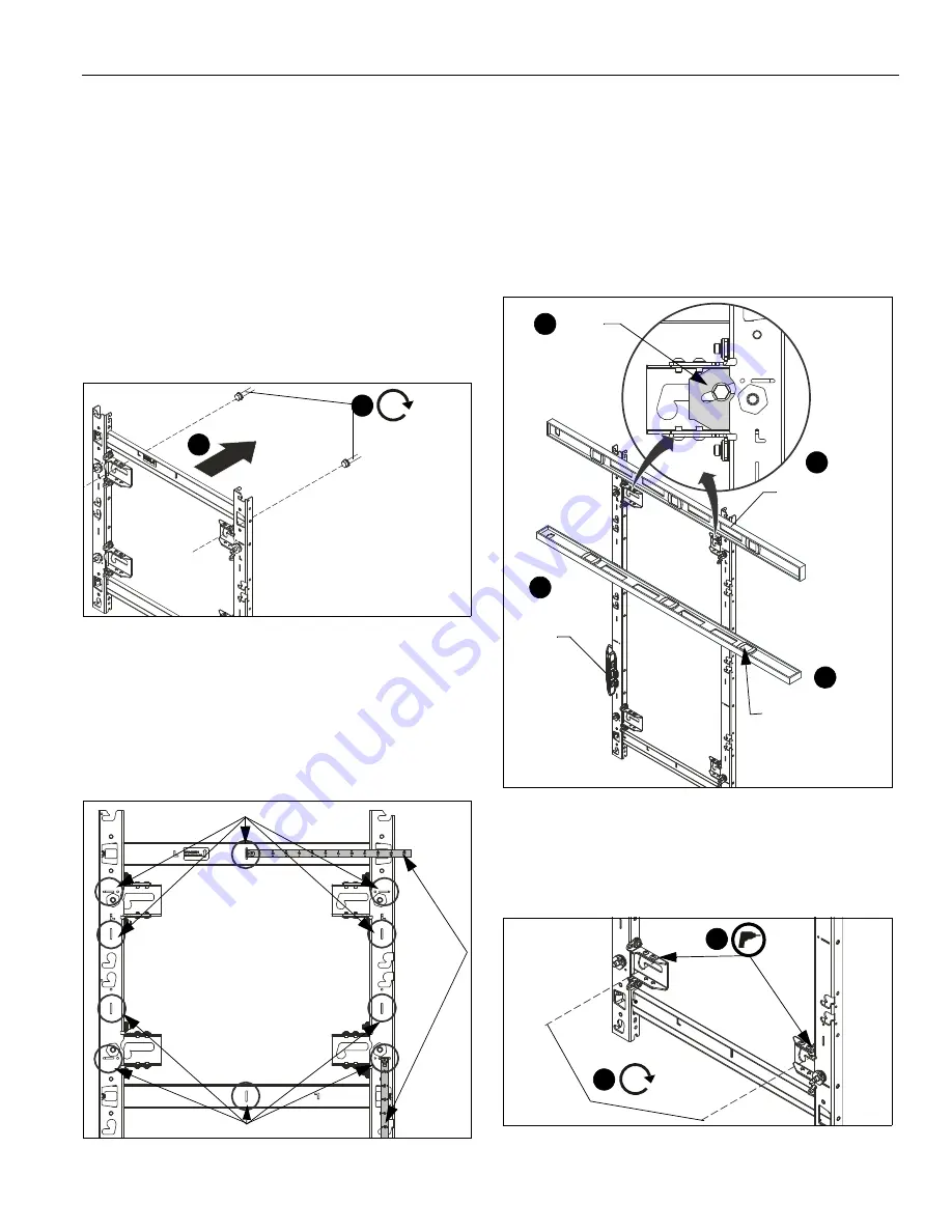
Partially install two fasteners into wall, but do NOT
completely tighten to wall. (See Figure 7)
NOTE:
(OPTIONAL)
If more LED screens need to be added to
the top or bottom of the screen configuration, add
TILVABPT vertical connector kit (not included) to top or
bottom of wall mount following instructions in the
(OPTIONAL) Adding Vertical Connector Kit
. If you
are NOT adding the TILVABPT connector kit, proceed
to
Step 5
.
NOTE:
Utilizing the two adjustment washers (A) allows the
installer to pre-install the top mounting fasteners and
hang the mount from them utilizing the mounting slots.
This allows the weight of the mount to be held by the
mounting bolts and not the installer during installation.
Figure 7
5.
Hang wall mount, aligning upper mounting slots over
fasteners, and adjust side-to-side for proper location. (See
Figure 7)
NOTE:
The horizontal slots located along the vertical mount
pieces (and vertical slots located along the horizontal
mount pieces) are the center-of-screen indicators to
illustrate where the center of each LED screen will be
located, and can be used to hold a tape measure tab
while measuring. (See Figure 8)
Figure 8
6.
Lay levels across flat of the mounting holes and center-of-
screen indicators, and vertically along side of mount to
ensure wall mount is square and level. (See Figure 9)
7.
Slide adjustment washers (A) behind head of upper fasteners
in mount and tighten mount in place. (See Figure 9)
NOTE:
It may be easier to insert the adjustment washers (A)
by slightly lifting up on the mount to relieve pressure on
the washers. As the adjustment washers are inserted
behind the upper fasteners the mount will rise up, and
the washers will hold it in place. Hold the washers in
place by hand while tightening the fasteners.
Figure 9
8.
Drill lower pilot holes (see Table 1 for size) at attachment
locations and follow fastener information (appropriate for
wall type) located in Table 1. (See Figure 10)
9.
Install two fasteners through lower part of mount and
tighten. (See Figure 10)
Figure 10
4
5
x 2
[TIL1X2PT shown as example]
Center-of-screen indicators
Center-of-screen indicators
Tape
Measure
Level placed
across flat of
mounting holes
Level along
side of
mount
Level placed along
center-of-screen
indicators
6
6
7
(A) x 2
6
9
x 2
8
x 2
Summary of Contents for CHIEF PT Series
Page 16: ...Installation Instructions TIL1X2PT TIL1X3PT TIL1X4PT TILVABPT 16 ...
Page 25: ...Installation Instructions TIL1X2PT TIL1X3PT TIL1X4PT TILVABPT 25 ...
Page 26: ...TIL1X2PT TIL1X3PT TIL1X4PT TILVABPT Installation Instructions 26 ...
Page 27: ...Installation Instructions TIL1X2PT TIL1X3PT TIL1X4PT TILVABPT 27 ...


