RMF3/RMT3/RLF3/RLT3
Installation Instructions
14
2.
Select correct screws, nesting spacers (if necessary) and
universal washers (if required) from the hardware bag (A-L)
and attach brackets to back of screen. (See Figure 9)
IMPORTANT ! :
The M8 screws do
NOT
require a
washer. Use the universal washer (MB) only with M4, M5,
and M6 screws.
NOTE:
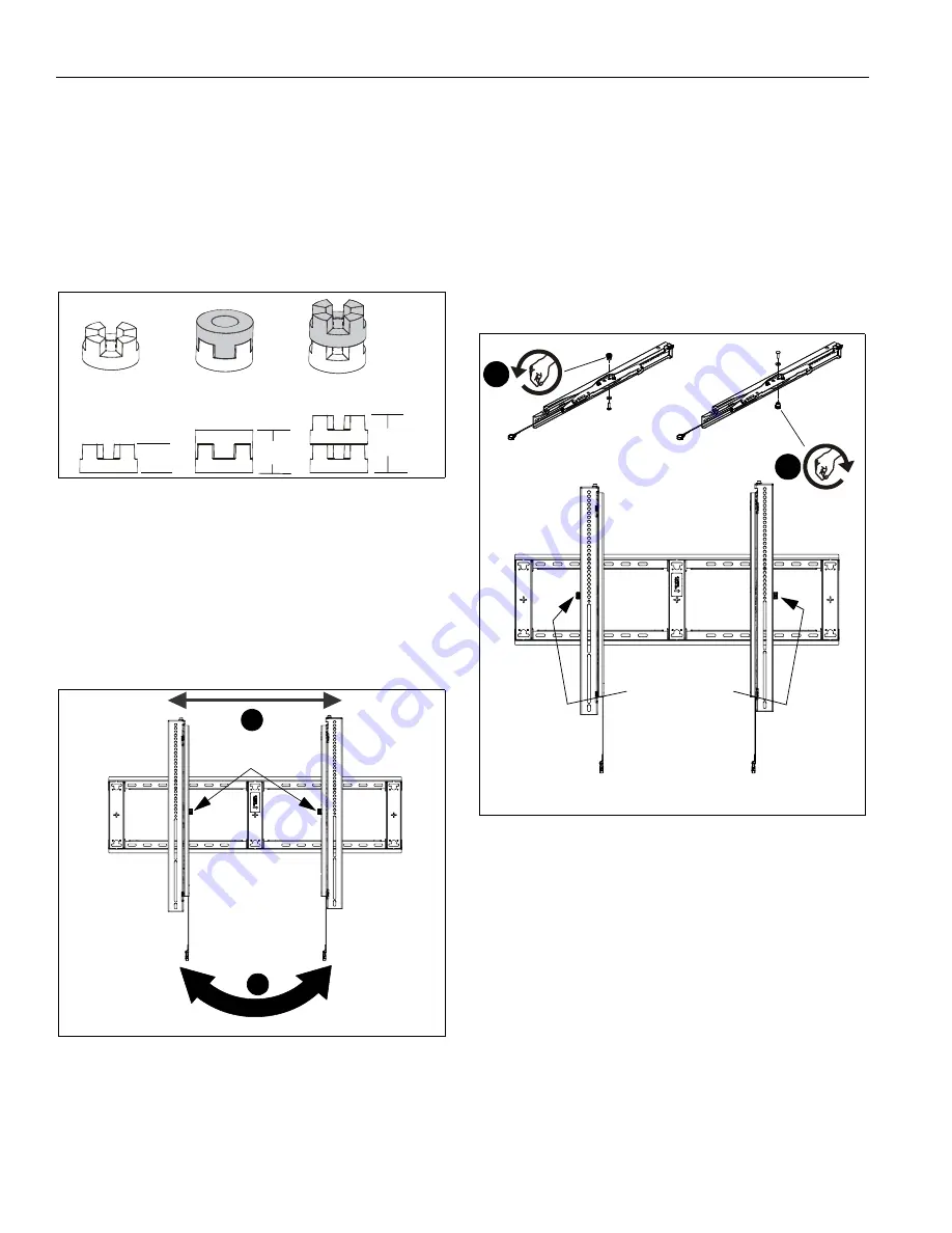
The nesting spacers (MA) may be used separately, or
put two together in different configurations to create
different size spacers. (See Figure 10)
Figure 10
Switching Interface Brackets (Optional)
If an installation situation makes adjusting the location of
interface brackets necessary, there are several options.
1.
The wall brackets may be adjusted side to side at the point
of attachment. (See Figure 11)
2.
The location of the left and right interface brackets (S and T
or U and V) may be switched, with the knobs on the RMT3/
RLT3 interface brackets (U and V) facing the inside of the
mount. (See Figure 11)
Figure 11
3.
If necessary, the tilt interface bracket knobs may be
switched to allow the interface brackets (U and V) to be
reversed. (See Figure 12)
a. Remove display from mount.
b. Remove interface brackets from display.
c. Hold the right interface bracket horizontally, tightly
gripping it so that spacers do not move.
d. Remove the knob and screw.
e. Replace the knob and screw in the opposite order, with
the knob on the inside of the bracket.
f. Switch the right interface bracket to the left side of the
wall mount.
NOTE:
Make sure the spacers on the inside of the interface
brackets remain in place when removing and replacing
the interface bracket knobs
Figure 12
(Single)
(Nested)
(Stacked)
0.375
[9.5]
0.563
[14.3]
0.750
[19.1]
1
2
Knobs
[Brackets U and V shown]
(RLT3 shown)
3e
Knobs to outside
of brackets
[Brackets U and V shown]
3d
(RLT3 shown)


