background image

Owner’s Manual of DA2131-V1 

- 13 - 


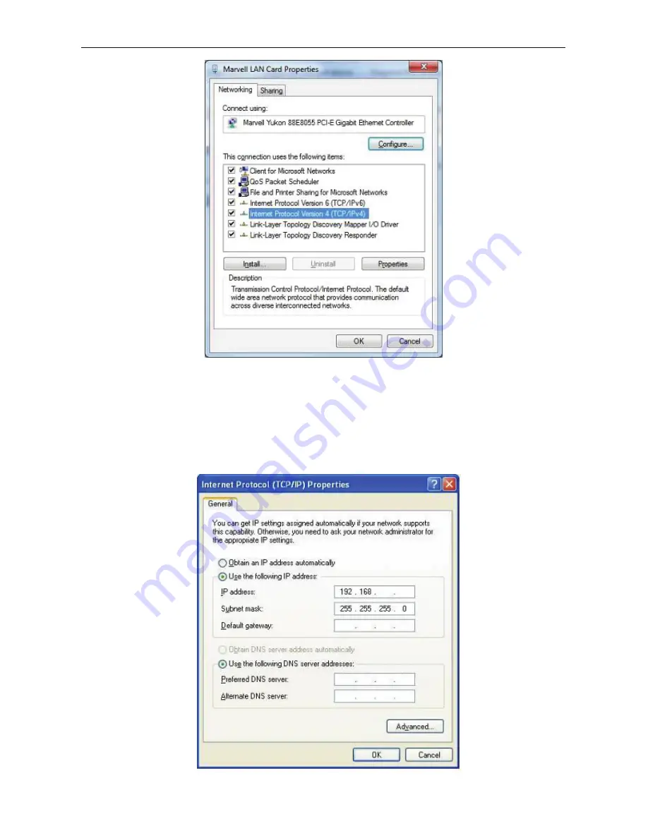
Figure 3-4 


4.


Move mouse and click 

General


tab, Select 

Specify an IP address


and type in values as following 

example.  

IP Address: 

192.168.40.2

, or any IP address within

 192.168.40.2

 to 

192.168.40.251

 is good to connect 

to the Outdoor NWAP. IP Subnet Mask:


255.255.255.0


Figure 3-5 

40 

Summary of Contents for DA2131-V1

Page 1: ... i Outdoor 802 11n Wireless Access Point P N DA2131 V1 Owner s Manual 1308197 Rev B ...

Page 2: ...ircuit different from that to which the receiver is connected Consult the dealer or an experienced radio TV technician for help Reprinted from the Code of Federal Regulations 47 part 15 193 1993 Washington DC Office of the Federal Register National Archives and Records Administration U S Government Printing Office Canadian Department of Communications This digital apparatus does not exceed the Cla...

Page 3: ...0 Protection requirements for electromagnetic compatibility in Article 3 1b Testing for electromagnetic compatibility in EN 301 489 1 EN 301 Testing according to 489 17 Effective use of the radio spectrum as in Article 3 2 Testing for radio test suites according to EN 300 328 2 WARNING TO PREVENT FIRE OR SHOCK HAZARD DO NOT EXPOSE THIS PRODUCT TO RAIN OR MOISTURE THE UNIT MUST NOT BE EXPOSED TO DR...

Page 4: ... the AC outlet to which this device is connected This is to avoid damaging the equipment by local lightning strikes and other electrical surges Operate this product only from the type of power source indicated on the product s marking label If you are not sure of the type of power supplied to your home consult your dealer or local power company Upon completion of any service or repairs to this pro...

Page 5: ...your DA2131 V1 from web browser 10 Chapter 4 Basic System Settings 16 Setup Wizard 16 DHCP 16 Static 17 PPPOE 18 L2TP 19 PPTP 20 Configure Wireless Settings 22 Operation Mode 23 Internet Settings 24 LAN Settings 26 VPN Passthrough 28 Advanced Wireless Settings 31 Security 33 WDS 42 Status 49 Firewall 52 Port Forwarding 53 Administration 57 Firmware Update 58 Settings Management 59 System Log 61 Ap...

Page 6: ... vi ...

Page 7: ... 150Mbps The radio coverage is also designed specifically for outdoor use To secure the wireless communication the Outdoor N WAP supports the most up to date encryption 64 128 bit WEP WPA WPA2 WPA PSK WPA2 PSK and 802 1x authority to secure and protect your wireless LAN MAC filtering and SSID broadcast control are provided to consolidate the wireless network security and prevent unauthorized wirel...

Page 8: ...ns LED State Meaning Power On System On Off System Off WLAN On Wireless Radio ON Off Wireless Radio Off Blinking Data is transmitting or receiving on the wireless WAN On Port linked Off No link Blinking Data is transmitting or receiving on the WAN interface LAN On Port linked Off No link Blinking Data is transmitting or receiving on the LAN interface Power LED Wireless LAN LED WAN Port LED LAN Por...

Page 9: ... 5 cable Supports auto sensing on 10 100M speed and half full duplex complys with IEEE 802 3 802 3u respectively WAN The RJ 45 jack allows WAN connection through a Category 5 cable Supports auto sensing on 10 100M speed and half full duplex complys with IEEE 802 3 802 3u respectively 1 For External Antenna Mode you MUST physically attach antenna before powering on 2 When using an external antenna ...

Page 10: ...PoE Injector Figure 1 5 Label of PoE Injector PoE Reset Button Figure 1 6 Reset Button of PoE Injector Active Time Reset Push and hold the reset button of POE injector about 5 10 seconds to reset the configuration parameters to factory defaults Reset Button 3 Use only for DA2131 V1 ...

Page 11: ... Do not use a metal ladder Do not work on a wet or windy day Wear shoes with rubber soles and heels rubber gloves long sleeved shirt or jacket 5 When the system is operational avoid standing directly in front of it Strong RF fields are present when the transmitter is on 2 1 3 Installation Precautions To avoid damage to the DA2131 V1 while you are installing it please read and follow these installa...

Page 12: ...2 1 Installation Steps Step 1 Push the latch in the bottom of DA2131 V1 to remove the sliding cover Figure 2 1 Move the cover Step 2 Plug the RJ 45 Ethernet cable into the LAN Port of DA2131 V1 Figure 2 2 Cable Connection RJ 45 8P8C Ethernet cable is required ...

Page 13: ...ower cord into the DC port and plug the other side of the RJ 45 cable from STEP 2 into the POE port of the PoE injector DC Insert adapter DC power cord POE This jack is connected to LAN port of the Outdoor N WAP with the supplied Cat5 cable LAN This jack is connected to LAN side PC Hub or Router ADSL modem device with a Cat5 cable Figure 2 4 Connect to PoE Injector To DA2131 V1 ...

Page 14: ...It will take about 50 seconds to complete the boot up sequence after powering on the Outdoor N WAP Power LED will be active and after that the WLAN Activity LED will be flashing to show the WLAN interface is enabled and working now To avoid lightening strike damage consider installing a lightening arrestor between the NWAP and PoE injector ...

Page 15: ...If you prefer to use the external antenna with SMA type connector for your application instead of the built in directional antenna please follow the steps below Step 1 Connect your antenna with the SMA type connector on the bottom of DA2132 V1 Step 2 Power on the DA2131 V1 and then go to Wireless Settings Basic to configure the Antenna Switch from Internal to External 1 If you are going to use an ...

Page 16: ...Default IP Subnet Mask 255 255 255 0 WEB login User Name admin WEB login Password admin 3 1 Connecting to the Outdoor NWAP For OS of Microsoft Windows 2000 XP 1 Click the Start button and select Settings then click Control Panel The Control Panel window will appear 2 Move mouse and double click the right button on Network and Dial up Connections icon Move mouse and double click the Local Area Conn...

Page 17: ...ay need the Microsoft Windows CD to complete the installation Close and go back to Network dialog box after the TCP IP installation 6 Select TCP IP and click the properties button on the Network dialog box Figure 3 2 7 Select Specify an IP address and type in values as following example IP Address 192 168 40 2 or any IP address within 192 168 40 2 to 192 168 40 251 is good to connect to the Outdoo...

Page 18: ...ndow will appear 2 Move mouse and double click the right button on Network Connections item The Network Connections window will appear Double click Local Area Connection icon then User Account Control window shown Right click Continue button to set properties 3 In Local Area Connection Properties window Choose Networking tab move mouse and click Internet Protocol Version 4 TCP IPv4 then click Prop...

Page 19: ... and click General tab Select Specify an IP address and type in values as following example IP Address 192 168 40 2 or any IP address within 192 168 40 2 to 192 168 40 251 is good to connect to the Outdoor NWAP IP Subnet Mask 255 255 255 0 Figure 3 5 40 2 ...

Page 20: ... Protocol dialog box then click OK button to install the TCP IP protocol it may need the Microsoft Windows CD to complete the installation Close and go back to Network dialog box after the TCP IP installation 6 Select TCP IP and click the properties button on the Network dialog box 7 Select Specify an IP address and type in values as following example IP Address 192 168 40 2 or any IP address with...

Page 21: ...web browser has been set to a proxy Go to Tools menu Internet Options Connections LAN Settings in the screen that appears cancel the Using Proxy checkbox and click OK to finish it After you enter the username and password the main screen appears as Figure 3 8 Figure 3 8 Web UI Screenshot The next chapter will introduce the functions of the web UI 40 252 40 252 ...

Page 22: ...e 4 1 Setup Wizard Click Next button to next step for Internet connection settings There are five options DHCP Static Mode PPPOE L2TP PPTP for Internet connection on WAN port a DHCP Auto Config If your ISP provides the DHCP service please choose Dynamic IP type and the NWAP will automatically obtain IP parameters from your ISP You can see the page as follows Figure 4 2 Step 1 DHCP ...

Page 23: ...ll appear shown as following Figure 4 3 Step 1 Static Mode The page includes the following fields Object Description IP Address Enter the IP address in dotted decimal notation provided by your ISP Subnet Mask Enter the subnet Mask in dotted decimal notation provided by your ISP usually is 255 255 255 0 Default Gateway Optional Enter the gateway IP address in dotted decimal notation provided by you...

Page 24: ...sword Fill in the password again for verification Operation Mode Keep Alive Keep the PPPoE connection all the time Please also configure the Redial Period field On Demand Please configure the Idle Time field When time is up the PPPoE connection will disconnect The connection will re connect when any outgoing packet arise Manual Let user connect the PPPoE connection manually Sometimes the connectio...

Page 25: ...ission among the connection User can use embedded L2TP client supported by this router to make a VPN connection If you select the L2TP support on WAN interface fill in the IP address for it User Name Password Enter the User Name and Password provided by your ISP These fields are case sensitive Address Mode Static To configure the IP address information by manually please fill in the related settin...

Page 26: ...ll in the default gateway for WAN interface out going data packets Operation Mode Keep Alive Keep the L2TP connection all the time Please also configure the Redial Period field Manual Let user connect the L2TP connection manually e PPTP If your ISP provides PPTP connection please select PPTP option And enter the following parameters Figure 4 6 Step1 PPTP ...

Page 27: ...re case sensitive Address Mode Static To configure the IP address information by manually please fill in the related setting at below Dynamic The option allows the machine to get IP address information automatically from DHCP server on WAN side IP Address Fill in the IP address for WAN interface Subnet Mask Fill in the subnet mask for WAN interface Default Gateway Fill in the default gateway for W...

Page 28: ...less you notice interference problems with another nearby access point Network Name SSID Enter a value of up to 32 characters The same name of SSID Service Set Identification must be assigned to all wireless devices in your network The default SSID is set to be Legrand WiFi This value is case sensitive For example LEGRAND is NOT the same as Legrand Channel Bandwidth Select the operating channel wi...

Page 29: ...ces are bridged into a single Bridge interface b Gateway The Gateway mode allows that the first Ethernet port is treated as WAN port and the Ethernet port and the wireless interface are bridged together and are treated as LAN ports c Wireless ISP The Wireless ISP mode allows that the wireless interface is treated as WAN port and the Ethernet ports are LAN ports ...

Page 30: ...cimal notation provided by your ISP usually is 255 255 255 0 Default Gateway Optional Enter the gateway IP address in dotted decimal notation provided by your ISP Primary Secondary DNS Optional Enter one or two DNS addresses in dotted decimal notation provided by your ISP b DHCP Object Description Host Name This option specifies the Host Name of the Router MAC Clone Take NIC MAC address of PC on L...

Page 31: ...efault Gateway Fill in the default gateway for WAN interface out going data packets Operation Mode Keep Alive Keep the L2TP connection all the time Please also configure the Redial Period field Manual Let user connect the L2TP connection manually e PPTP Object Description PPTP Server IP Address Allow user to make a tunnel with remote site directly to secure the data transmission among the connecti...

Page 32: ...amic The option allows the machine to get IP address information automatically from DHCP server on WAN side IP Address Fill in the IP address for WAN interface Subnet Mask Fill in the subnet mask for WAN interface Default Gateway Fill in the default gateway for WAN interface out going data packets Operation Mode Keep Alive Keep the PPTP connection all the time Please also configure the Redial Peri...

Page 33: ...in the start IP address to allocate a range of IP addresses client with DHCP function set will be assigned an IP address from the range End IP Address Fill in the end IP address to allocate a range of IP addresses client with DHCP function set will be assigned an IP address from the range Lease Time Fill in the lease time of DHCP server function 802 1d Spanning Tree Select enable or disable the IE...

Page 34: ...ormation Figure 4 11 DHCP Clients 4 3 4 VPN Passthrough Figure 4 12 VPN Passthrough The page includes the following fields Object Description L2TP Passthrough Select enable or disable the L2TP pass through function from pull down menu IPSec Passthrough Select enable or disable the IPSec pass through function from pull down menu PPTP Passthrough Select enable or disable the PPTP pass through functi...

Page 35: ...ess OFF button to turn off wireless RF radio Click Wireless ON button to turn on wireless RF radio Antenna Switch Select Internal antenna or External antenna for using The default is using Internal antenna Wireless Mode Click to select wireless mode from pull down menu SSID It is the wireless network name The SSID can be 32 bytes long User can use the default SSID or change it ...

Page 36: ... MBSSID Example The client connected with BSSID 1 When enable this function it will not connect with BSSID 2 Only can access between clients with SSID 1 BSSID Show the MAC address of Wireless interface Frequency Channel Select the wireless communication frequency channel from pull down menu Operating Mode Select Mixed Mode for 11b g n mode or Green Field for 11n mode Channel BandWidth Select the o...

Page 37: ...e as AP mode Beacon Interval Beacons are the packets sending by Access point to synchronize the wireless network The beacon interval is the time interval between beacons sending by this unit in AP or AP WDS operation The default and recommended beacon interval is 100 milliseconds Data Beacon Rate DTM This is the Delivery Traffic Indication Map It is used to alert the clients that multicast and bro...

Page 38: ... device or in areas where the clients are far apart and can detect only the device and not each other You can enter a setting ranging from 0 to 2347 bytes TX Power The default TX power is 100 In case of shortening the distance and the coverage of the wireless network input a smaller value to reduce the radio transmission power For example input 80 to apply 80 Tx power Short Preamble Default Disabl...

Page 39: ...A2131 V1 33 4 4 3 Security a Disable Figure 4 15 Wireless Security Settings If you set Security Mode to Disable the wireless data transmission will not include encryption to prevent from unauthorized access and monitoring ...

Page 40: ...t Security Mode to OPEN WEP or SHARED WEP please fill in the related configurations at below Object Description Default Key Specify a Key number for effective WEP Keys 1 4 When you select the encryption type as WEP please input 5 13 ASCII 10 or 26 HEX characters for WEP Key ...

Page 41: ...set Security Mode to OPEN WEP or SHARED WEP please fill in the related configurations at below Object Description Default Key Specify a Key number for effective WEP Keys 1 4 When you select the encryption type as WEP please input 5 13 ASCII 10 or 26 HEX characters for WEP Key ...

Page 42: ... RADIUS Server s IP Address provided by your ISP Port Enter the RADIUS Server s port number provided by your ISP The Default is 1812 Shared Secret Enter the password that the Wireless Router shares with the RADIUS Server Session Timeout Session timeout interval is for 802 1x re authentication setting Set to zero to disable 802 1x re authentication service for each session Session timeout interval ...

Page 43: ...ollowing fields Object Description WPA Cipher Suite Select TKIP AES or TKIPAES for WPA algorithms Pre Shared Key Please fill in a passphrase like test wpa 123 or a hexadecimal string like 65E4 E123 456 E1 Key Renewal Interval Please fill in a number for Group Key Renewal interval time ...

Page 44: ...me PMK Cache Period Only valid in WPA2 security Set WPA2 PMKID cache timeout period after time out the cached key will be deleted PMK Cache Period unit is minute Pre Authentication Only valid in WPA2 security The most important features beyond WPA to become standardized through 802 11i WPA2 are Pre authentication which enables secure fast roaming without noticeable signal latency Shared Secret Ent...

Page 45: ...less Router shares with the RADIUS Server Session Timeout Session timeout interval is for 802 1x re authentication setting Set to zero to disable 802 1x re authentication service for each session Session timeout interval unit is second and must be larger than 60 Idle Timeout Enter the idle timeout in the column g WPA2 PSK Figure 4 21 WPA2 PSK The page includes the following fields Object Descripti...

Page 46: ...r the RADIUS Server s port number provided by your ISP The Default is 1812 Shared Secret Enter the password that the Wireless Router shares with the RADIUS Server Session Timeout Session timeout interval is for 802 1x re authentication setting Set to zero to disable 802 1x re authentication service for each session Session timeout interval unit is second and must be larger than 60 Idle Timeout Ent...

Page 47: ...Description Policy Select the Disabled Allow or Reject of drop down menu choose wireless access control mode This is a security control function only those clients registered in the access control list can link to this NWAP Add a station MAC Fill in the MAC address of client to register this AP router access capability ...

Page 48: ...at connect to other units in Repeater The MAC addresses of WDS peers must be configured on the Wireless 11n Access Points Repeaters Basically this mode is used when you have a 2 4GHz outdoor router with more than one WDS link to other AP Repeaters Note In this mode wireless clients will not be able to connect to the 2 4GHz outdoor router directly Step 1 In the Basic Wireless Settings configure Wir...

Page 49: ... other For example enter the MAC Address of the remote site to the settings of local site and enter the MAC Address of the local site to the settings of remote site 3 The Encryption Type must be the same in both sites if available c AP WDS Repeater Mode Repeater mode allows user to operate as a wireless repeater extending the range for remote wireless clients and connecting them to an AP connected...

Page 50: ...Owner s Manual of DA2131 V1 44 Step 1 In the Basic Wireless Settings configure Wireless Mode to AP WDS Figure 4 26 Wireless Mode AP WDS ...

Page 51: ...e channel must be the same in both sites You should fix the channel from AutoSelect to a static one 2 You must fill in the MAC Address by each other For example enter the MAC Address of the remote site to the settings of local site and enter the MAC Address of the local site to the settings of remote site 3 The Encryption Type must be the same in both sites if available ...

Page 52: ...te survey you need to configure the DA2131 V1 as AP Client mode in the Basic Wireless Settings page as following Step 1 Go to Wireless Settings Basic select the Wireless Moe to AP Client Figure 4 28 Basic Wireless Settings Step 2 Go to Wireless Settings Site Survey to scan the AP Select the AP that you choose to connect and then click Next ...

Page 53: ... shows the signal strength of current AP Channel It show the current channel of AP occupied Encrypt It shows the encryption status Wireless Mode It show the wireless mode of AP Step 3 If the AP has encryption setting it will pop out a window for you filling the encryption setting Please fill up the code in this case the code was 1234567890 and click Apply to connect with the AP ...

Page 54: ...Owner s Manual of DA2131 V1 48 Figure 4 30 Site Survey 2 ...

Page 55: ...Owner s Manual of DA2131 V1 49 Step 4 After connected with AP you can open Status page under Administrator to check link status Figure 4 31 AP Status ...

Page 56: ...e effect function after change Step 2 To add a new device If the wireless adapter supports Wi Fi Protected Setup WPS you can establish a wireless connection between wireless adapter and Router using either Push Button Configuration PBC method or PIN method To build a successful connection by WPS you should also do the corresponding configuration of the new device for WPS function meanwhile I By Pu...

Page 57: ...equipped on the adapter directly for 2 or 3 seconds Or you can click the WPS button with the same function in the configuration utility of the adapter 1 Step 1 2 should process within two minutes 2 DA2131 V1 only supports PBC method Step 3 Wait for a while until the connection established to complete the WPS configuration ...

Page 58: ...IC to restrict data transmission Dest IP Address Fill in the IP address of destination to restrict data transmission Source IP Address Fill in the IP address of source to restrict data transmission Protocol Select the protocol that you want to restrict There are four options None TCP UDP and ICMP Dest Port Range Fill in the start port and end port number of destination to restrict data transmissio...

Page 59: ...Reset button to clear selected items 4 5 2 Port Forwarding Figure 4 38 Port Forwarding The page includes the following fields Object Description Port Forwarding Select Enable or Disable the Port Forwarding function IP Address To forward data packets coming from WAN to a specific IP address that hosted in local network behind the NAT firewall fill in the IP address Port Range To forward data packet...

Page 60: ...d data packets coming from WAN to a specific IP address that hosted in local network behind the NAT firewall fill in the public port Private Port To forward data packets coming from WAN to a specific IP address that hosted in local network behind the NAT firewall fill in the private port Protocol Specify protocol TCP UDP TCP or UDP Comment Make a comment for the virtual server policy Delete Select...

Page 61: ... Security The page includes the following fields Object Description Remote management Select Deny or Allow for remote management function Ping form WAN Filter Select Disable or Enable for Ping permit from WAN SPI Firewall Select Disable or Enable for SPI firewall function ...

Page 62: ... fields Object Description Keyword Fill in a word for Webs Host Filter policy URL Fill in a URL string for URL filter Then click Add button to save the URL filter policy or click Reset button to clear the field Delete Click Delete button to delete all that you selected Reset Click Reset button to clear selected items ...

Page 63: ...Owner s Manual of DA2131 V1 57 4 6 Administrator 4 6 1 Management Figure 4 42 System Management The page includes the following fields ...

Page 64: ...ill in a number to decide the synchronization frequency with NTP server Dynamic DNS Provider Click the drop down menu to pick up the right DDNS provider you registered Account Fill in the account of DDNS you registered Password Fill in the password of DDNS you registered DDNS Fill in the domain name that you registered 4 6 2 Upload Firmware Figure 4 43Upload F W The page includes the following fie...

Page 65: ...cription Export Button Click Export button to export the current configuration to your PC Settings file location Click Browse button to select the configuration file from your PC then click Import button to update the configuration Load Default Button Click the Load Default button to reset the configuration parameter to factory defaults ...

Page 66: ...Owner s Manual of DA2131 V1 60 4 6 4 Status This page shows the current status and some basic settings of the device includes system info Internet Configurations and Local Network Figure 4 45 Status ...

Page 67: ...s page is used to view the system logs Figure 4 46 System Log The page includes the following fields Object Description Refresh Click the Refresh button to refresh the log shown on the screen Clear Click the Clear button to clear the log display screen ...

Page 68: ... case PoE Passive PoE 12V DC Reset Button on PoE Injector LAN RJ 45 Pin Assignment PIN 4 PIN 7 8 PIN 5 Reset Wireless Interface Specification Frequency Band 2 4 2 4835GHz Modulation Transmission Emission Type DSSS OFDM Data modulation type OFDM with BPSK QPSK 16 QAM 64 QAM DBPSK DQPSK CCK Data Rate 802 11b 11 5 5 2 and 1 Mbps with auto rate fall back 802 11g 54 48 36 24 18 12 9 and 6Mbps 802 11n 2...

Page 69: ...re LAN Built in DHCP server supporting static IP address distributing Support UPnP Support IGMP Proxy DNS Proxy Support 802 1d STP Spanning Tree Protocol WAN Protocol Static IP DHCP Dynamic IP PPPoE PPTP L2TP VPN Passthrough PPTP L2TP IPSec Operating Mode Bridge Gateway Ethernet Converter WISP Firewall NAT firewall with SPI Stateful Packet Inspection Built in NAT server supporting Port Forwarding ...

Reviews: