IT
Daker DK 1, 2, 3 kVA
53
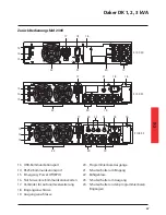
Nel retro del gruppo di continuità sono predisposti i seguenti collegamenti:
• Prese di Uscita [19], connettore di ingresso [18]: collegare a questi connettori il cavo di
alimentazione ed i cavi di uscita in dotazione.
• Presa per collegamento interfaccia seriale computer tipo RS232 (9 poli femmina) [14]: da
utilizzarsi nel caso si voglia sfruttare il software diagnostica e gestione shutdown.
• Presa per il collegamento interfaccia USB [13]: da utilizzarsi nel caso si voglia connettere l’UPS
con collegamento tramite cavo USB.
• Predisposizione per collegamento batterie aggiuntive [17].
AVVERTENZA
Per motivi di sicurezza si consiglia di non modificare i cavi forniti; inoltre è necessario
assicurarsi che la presa di rete a cui si collega il gruppo di continuità abbia una sicura
connessione al circuito di terra ed un’adeguata protezione come richiesta da normativa.
AVVERTENZA
La presa di alimentazione di rete, o il dispositivo di sezionamento, devono essere installati in
prossimità dell’apparecchiatura e devono essere facilmente accessibili.
Procedere all’installazione nel modo seguente:
1) Posizionare il gruppo di continuità in modo che le feritoie di ventilazione non risultino ostruite.
2) Collegare al connettore di Ingresso [18] il cavo di alimentazione ed i cavi di uscita ai relativi
connettori [19].
3) Collegare i carichi ai cavi di uscita, verificando che gli interruttori dei vari utilizzatori siano spenti.
4) Collegare la spina di alimentazione ad una presa di corrente adeguata alla tensione e alla
corrente richieste.
Accensione
1) Chiudere l’interruttore di protezione ingresso posto su retro dell’UPS[21]. L’UPS accenderà e I
LED Verdi
, e
indicheranno che l’ingresso rete e l’ingresso bypass sono normali. Il
display LCD indicherà OFF dopo pochi secondi.
2) Ora l’UPS sarà in Modo Bypass ed eseguirà automaticamente il self-test. Se non appare nessun
messaggio di anomalia, la pre accensione dell’UPS ha avuto successo ed il carica batterie inizierà
a caricare le batterie.
3) Premere il tasto di accensione dell’UPS
[7] per circa tre secondi. Il Cicalino suonerà due volte
ed il display cambierà stato su modalità RUN.
4) L’UPS è nuovamente in modalità self-test. Il Display mostrerà il messaggio TEST e l’UPS resterà in
modalità batterie per circa quattro secondi.
5) Se il self-test fallisce un codice od un messaggio di errore apparirà sul display.
6) Ora l’accesione dell’UPS è completa. Accertarsi che l’UPS sia collegato alla rete per una ricarica
di almeno 8 ore e che le batterie siano completamente cariche prima di connettere il carico da
proteggere.
Summary of Contents for Daker DK 1 kVA
Page 1: ... Part LE05334AD 09 13 01 GF Daker DK 1 2 3 kVA Manuel d installation Installation manual ...
Page 9: ...FR 9 Daker DK 1 2 3 kVA Configuration tower A1 A1 A1 A1 A3 A2 Step 1 Step 2 ...
Page 10: ...10 4 Installation UPS armoire batterie option A4 Step 1 Step 2 ...
Page 11: ...FR Daker DK 1 2 3 kVA 11 Configuration rack 19 B2 B1 S3 90 Step 1 Step 2 Step 3 Step 4 ...
Page 12: ...12 4 Installation Step 5 Step 6 ...
Page 15: ...FR Daker DK 1 2 3 kVA 15 R1 R2 S T U1 U2 U3 V ...
Page 18: ...18 6 Changement batteries Step 1 Step 2 ...
Page 19: ...FR Daker DK 1 2 3 kVA 19 Step 3 Step 4 3 100 50 Step 4 3 100 51 3 100 52 ...
Page 29: ...EN Daker DK 1 2 3 kVA 29 Tower configuration setup A1 A1 A1 A1 A3 A2 Step 1 Step 2 ...
Page 30: ...30 4 Installation UPS battery cabinet optional A4 Step 1 Step 2 ...
Page 31: ...EN Daker DK 1 2 3 kVA 31 B2 B1 S3 90 Step 1 Step 2 Step 3 Step 4 ...
Page 32: ...32 4 Installation Step 5 Step 6 ...
Page 35: ...EN Daker DK 1 2 3 kVA 35 R1 R2 S T U1 U2 U3 V ...
Page 38: ...38 6 Battery replacement Step 1 Step 2 ...
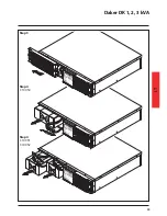
Page 39: ...EN Daker DK 1 2 3 kVA 39 Step 3 Step 4 3 100 50 Step 4 3 100 51 3 100 52 ...
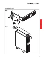
Page 49: ...IT Daker DK 1 2 3 kVA 49 Configurazione Tower A1 A1 A1 A1 A3 A2 Step 1 Step 2 ...
Page 50: ...50 4 Installazione UPS armadio batteria opzionale A4 Step 1 Step 2 ...
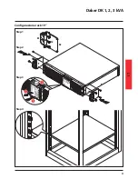
Page 51: ...IT Daker DK 1 2 3 kVA 51 Configurazione rack 19 B2 B1 S3 90 Step 1 Step 2 Step 3 Step 4 ...
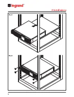
Page 52: ...52 4 Installazione Step 5 Step 6 ...
Page 55: ...IT Daker DK 1 2 3 kVA 55 R1 R2 S T U1 U2 U3 V ...
Page 58: ...58 6 Sostituzione batterie Step 1 Step 2 ...
Page 59: ...IT Daker DK 1 2 3 kVA 59 Step 3 Step 4 3 100 50 Step 4 3 100 51 3 100 52 ...
Page 69: ...DE Daker DK 1 2 3 kVA 69 Tower konfiguration A1 A1 A1 A1 A3 A2 Step 1 Step 2 ...
Page 70: ...70 4 Installation USV batteriefach option A4 Step 1 Step 2 ...
Page 71: ...DE Daker DK 1 2 3 kVA 71 Konfiguration rack 19 B2 B1 S3 90 Step 1 Step 2 Step 3 Step 4 ...
Page 72: ...72 4 Installation Step 5 Step 6 ...
Page 75: ...DE Daker DK 1 2 3 kVA 75 R1 R2 S T U1 U2 U3 V ...
Page 78: ...78 6 Batterien auswechseln Step 1 Step 2 ...
Page 79: ...DE Daker DK 1 2 3 kVA 79 Step 3 Step 4 3 100 50 Step 4 3 100 51 3 100 52 ...
Page 89: ...ES Daker DK 1 2 3 kVA 89 Configuración tower A1 A1 A1 A1 A3 A2 Step 1 Step 2 ...
Page 90: ...90 4 Instalación SAI armario batería opcional A4 Step 1 Step 2 ...
Page 91: ...ES Daker DK 1 2 3 kVA 91 Configuración rack 19 B2 B1 S3 90 Step 1 Step 2 Step 3 Step 4 ...
Page 92: ...92 4 Instalación Step 5 Step 6 ...
Page 95: ...ES Daker DK 1 2 3 kVA 95 R1 R2 S T U1 U2 U3 V ...
Page 98: ...98 6 Cambio de las baterías Step 1 Step 2 ...
Page 99: ...ES Daker DK 1 2 3 kVA 99 Step 3 Step 4 3 100 50 Step 4 3 100 51 3 100 52 ...
Page 109: ...RU 109 Daker DK 1 2 3 kVA Установка ИБП в конфигурации башня A1 A1 A1 A1 A3 A2 Шаг 1 Шаг 2 ...
Page 110: ...110 4 Монтаж ИБП БАТАРЕЙНЫЙ КАБИНЕТ ПОСТАВЛЯЕТСЯ ДОПОЛНИТЕЛЬНО A4 Шаг 1 Шаг 2 ...
Page 112: ...112 4 Монтаж Шаг 5 Шаг 6 ...
Page 115: ...RU Daker DK 1 2 3 kVA 115 R1 R2 S T U1 U2 U3 V ...
Page 118: ...118 6 Замена батареи Шаг 1 Шаг 2 ...
Page 119: ...RU Daker DK 1 2 3 kVA 119 Шаг 3 Шаг 4 3 100 50 Шаг 4 3 100 51 3 100 52 ...
Page 123: ......


