
4
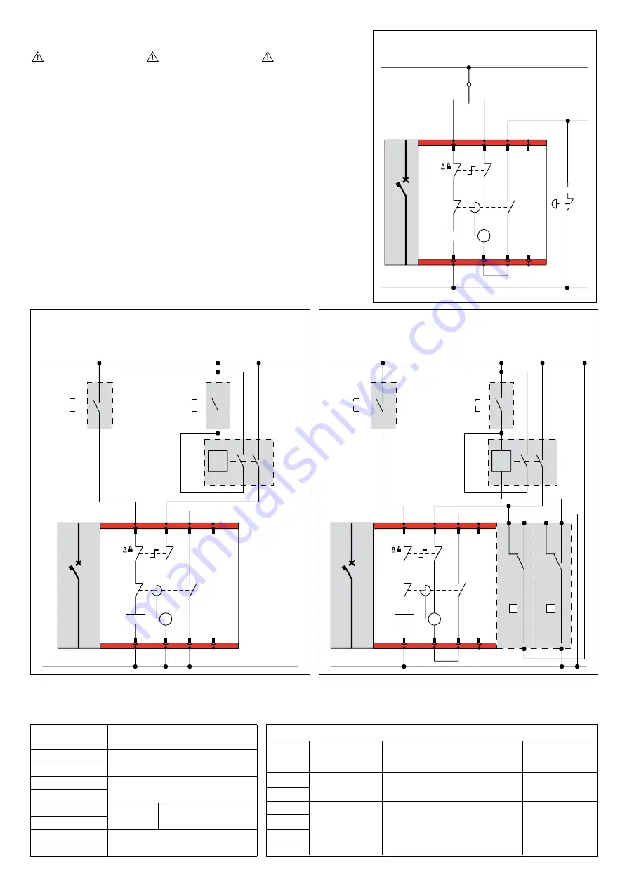
caRacteRistiques / TECHNICAL CHARACTERISTICS / PaRametRY tecHnicZne
temPs D’ouVeRtuRe totaL + ReaRmement
TOTAL OPENING TIME + RESET
cZas WYŁĄ ZaZBRoJenie
temPs De FeRmetuRe
CLOSING TIME
cZas ZaŁĄcZenia
Puissance aBsoRBee
START INPUT POWER
PoBÓR mocY
tension
VOLTAGE
NAPIĘCIE
24V cc
48V cc
24V ca
48V ca
110V ca
230V ca
2 s
2 s
≤ 100 ms
300 VA
≤ 100 ms
300 W
S1
(ii)
(ii)
(i)
S2
3
1
5
7
4
6
8
A
B
C
D
M
Q1
MAN
BC
2
S1
(ii)
(ii)
(i)
S2
3
1
5
7
4
6
8
A
B
C
D
M
Q1
MAN
BC
2
24
14
Wh
Wh
22
12
Rd
Rd
Bk
Bk
21
11
E
D
3
1
5
7
4
6
8
A
B
C
D
M
Q1
MAN
BC
2
C1
SE
S1
(ii)
(ii)
(i)
S2
3
1
5
7
4
6
8
A
B
C
D
M
Q1
MAN
BC
2
S1
(ii)
(ii)
(i)
S2
3
1
5
7
4
6
8
A
B
C
D
M
Q1
MAN
BC
2
24
14
Wh
Wh
22
12
Rd
Rd
Bk
Bk
21
11
E
D
3
1
5
7
4
6
8
A
B
C
D
M
Q1
MAN
BC
2
C1
SE
S1
(ii)
(ii)
(i)
S2
3
1
5
7
4
6
8
A
B
C
D
M
Q1
MAN
BC
2
S1
(ii)
(ii)
(i)
S2
3
1
5
7
4
6
8
A
B
C
D
M
Q1
MAN
BC
2
24
14
Wh
Wh
22
12
Rd
Rd
Bk
Bk
21
11
E
D
3
1
5
7
4
6
8
A
B
C
D
M
Q1
MAN
BC
2
C1
SE
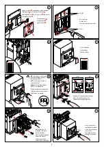
n.B.: Les schémas correspondent au disjoncteur en position ouverte et ressort du moteur chargé.
A
tt
.:
In the figures the C.b. is represented in open position, with spring’s motor loaded.
uwaga: Pozycje styków wewnątrz napędu pokazano przy wyłączonym wyłączniku i naciągniętej sprężynie.
utiLisation en inVeRseuRs
De souRce automatiques
attention:
s e l o n l a m o d a l i t é
d’utilisation du moteur,
c’est a dire:
• Sans déclencheur
ou
• Avec déclencheur
(26164-8;26181-4)
Le temps de commutation
entre ligne principale et
ligne secourue (temps entre
l’ouverture du disjoncteur
de la ligne principale et la
fermeture de celle de secours)
doit être enregistré de façon
à être supérieur ou égal
respectivement à :
• 6 sec
ou
• 0,5 sec
USE FOR AUTOMATIC
CHANGEOVER
Caution:
according to the use mode
of the motor that is:
• without tripping device
or
• w i t h t r i p p i n g d e v i c e
(26164-8;26181-4)
The changeover time between
main and secondary line (time
between the opening of the
breakers of the main line and
the closing of the breakers of the
secondary line and viceversa)
should be setted at a value
bigger or equal respectively to:
• 6 sec
or
• 0,5 sec
WsKaZania DLa ZmianY
automatYcZneJ
uwaga:
Z g o d n i e z t r y b e m
użytkowania silnika:
• Z wyłącznikiem
lub
• Bez wyłącznika
( 26164-8;26181-4)
Czas zmiany pomiędzy linią
główną, a linią dodatkową
(czas pomiędzy otwarciem
strumienia na linii głównej a
zamknięciem strumienia na
linii dodatkowej i odwrotnie)
powinien zostać ustawiony
na poziomie większym lub
równym:
• 6sekund
Lub
• 0,5 sekundy
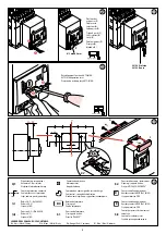
commande maintenue /
Switch Operated
sterowanie za pomocą łącznika 3 pozycyjnego
Réarmement volontaire / Volontary reset / Ręczne zazbrojenie
Fermeture
Closing
Załącz
Ouverture et charge
Open and charge
Wyłącz / Zazbrój
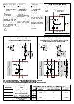
commande à impulsion / Push button Operated
sterowanie za pomocą przycisków
Réarmement automatique après déclenchement / Automatic reset after trip
automatyczne zazbrojenie napędu po wyzwoleniu wyłącznika
Ferme
Closing
Załącz
Ferme
Closing
Załącz
Ouverture et charge
Open and charge
Wyłącz / Zazbrój
Ouverture et charge
Open and charge
Wyłącz / Zazbrój
commande à impulsion / Push button Operated
sterowanie za pomocą przycisków
Réarmement volontaire / Volontary reset / Ręczne zazbrojenie
BoRne a caGe / LUG
ZacisK KLatKoWY
Fonction / FUNCTION
FunKcJa
1
Alimentation fermeture /
Closing power
supply
/ Załączanie źródła zasilania
2
3
Alimentation ouverture /
Opening power
supply
/ Odłączanie źródła zasilania
4
5
NO (250
Vac/2A)
Ressort chargé /
Spring loaded
/
Sprężyna naciągnięta
6
7
Pas connectés /
Not connected
/
Nie podłączone
8


